
Key Takeaways
- Torque sizing requires calculating blade weight x moment arm distance x safety factor (minimum 1.5)
- Minimum ratings range from 15 kN/m for 1.5MW turbines to 70 kN/m for 5MW turbines
- Dynamic torque can reach 1.5–2x static torque during motion — always size for the higher value
- Undersizing leads to catastrophic failure: gear damage, blade drops, and $200K+ in losses
- Hydraulic drives outperform electric for turbines above 2MW in field conditions
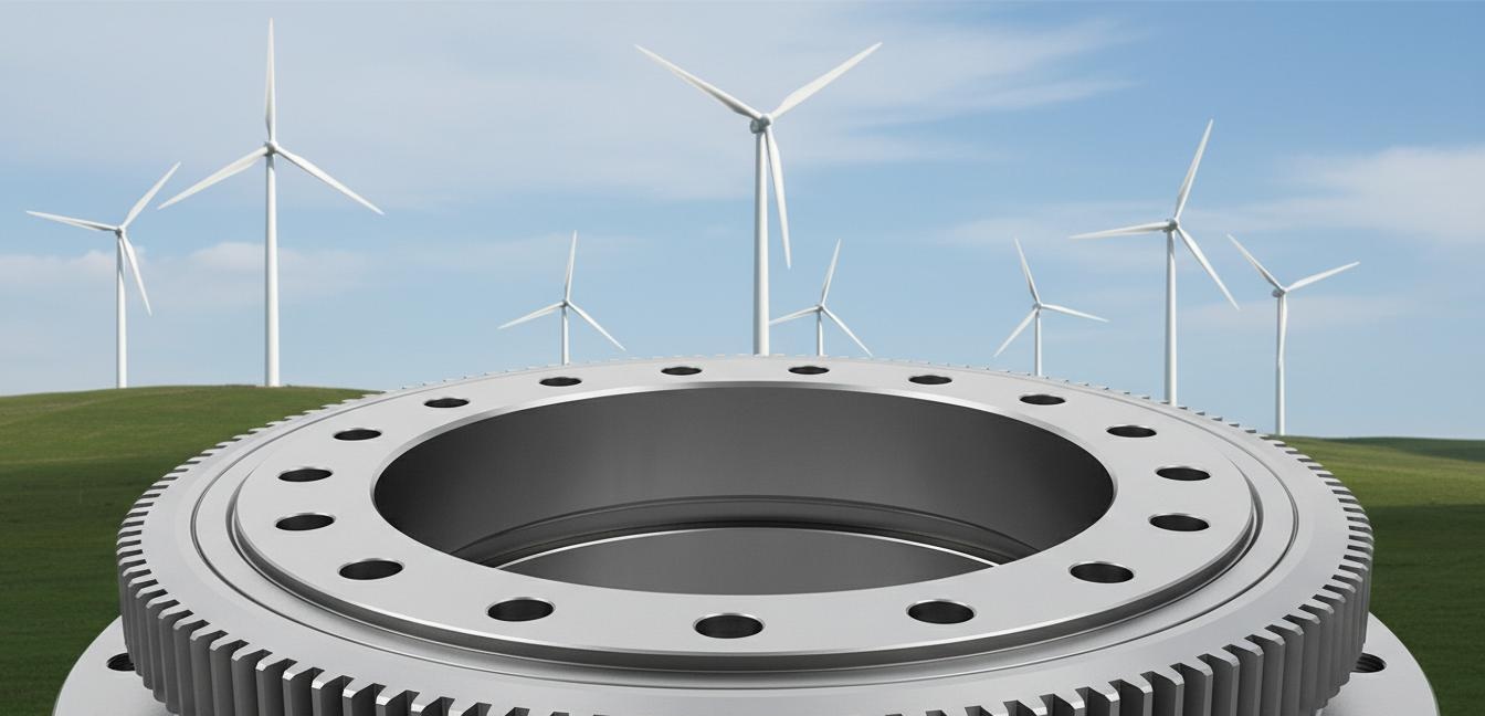
1. Why Wind Turbine Maintenance Places Unique Demands on Slewing Drives
I've spent over fifteen years working with slewing drives in heavy industrial applications, and I can tell you this: wind turbine maintenance is one of the most demanding environments you'll encounter. Unlike stationary industrial equipment, wind turbines operate in some of the harshest conditions on the planet — offshore platforms with salt spray, desert sites with sand abrasion, and alpine locations with temperatures swinging from -30 degrees C to +50 degrees C within the same day.
The slewing drive is the heart of any turbine maintenance operation. It's the component that rotates the nacelle, the hub, and more importantly, it controls the precise positioning of blades during replacement or repair. Get this wrong, and you're not looking at a minor inconvenience — you're looking at a catastrophic failure that can destroy a blade worth $300,000 or more.
What makes wind turbine maintenance so demanding? Let me break down the key factors:
- Extreme load variances: A single blade on a 5MW turbine can weigh 20,000 kg. That's 196,200 newtons of force that your slewing drive must handle — and that's before you account for wind gusts during the replacement process.
- Precision requirements: Blade attachment points must align within 2mm tolerance. Get it wrong and you risk bolt damage, metal fatigue, or blade failure during operation.
- Unpredictable environmental loads: Wind doesn't stop just because you're performing maintenance. Gusts up to 15 m/s can strike suddenly, imposing additional overturning moments on your slewing system.
- Accessibility constraints: In most turbine maintenance scenarios, you're working with limited space, limited crane reach, and zero margin for error. Your slewing drive must perform reliably the first time, every time.
The lesson here is simple: when you're dealing with turbine maintenance, the cost of your slewing drive is a tiny fraction of the risk you're managing. Never cheap out on torque rating — the math doesn't lie.
2. The Torque Calculation Formula for Turbine Blade Replacement
Here's the formula I use for every turbine maintenance project:
Torque (kN/m) = (Blade Weight x Moment Arm Distance x Safety Factor) / 1000
Let me walk you through each variable using a real example. Suppose you're replacing a blade on a 3MW turbine. The blade weighs 18,000 kg, and your crane's moment arm — the distance from the crane hook to the blade's center of gravity at the attachment point — measures 12 meters.
Step one: calculate the blade weight in newtons. 18,000 kg x 9.81 m/s^2 = 176,580 N.
Step two: calculate the moment force. 176,580 N x 12 m = 2,118,960 N/m.
Step three: apply your safety factor. For maintenance operations, I recommend a minimum of 1.5x — some operators use 2.0x, and I never argue with caution. 2,118,960 x 1.5 = 3,178,440 N/m.
Step four: convert to kilonewton-meters. 3,178,440 / 1000 = 3,178.44 kN/m. That's your peak torque requirement.
But this calculation assumes ideal conditions. In reality, you'll need to account for additional factors:
- Wind loading: Add 10–15% for expected wind loads during the positioning operation
- Dynamic amplification: Multiply by an additional 1.25x for inertia effects during acceleration/deceleration
- Shock loading: Add a further 1.1x for unexpected load spikes
When you factor all of these in, your 3,178 kN/m requirement quickly becomes 4,000+ kN/m. This is exactly why I always, always recommend erring on the high side. In my experience, the most common failure I've seen in the field isn't a mysterious technical problem — it's simple undersizing. Someone did the math, but they did it with assumptions that were too optimistic.
Let me give you another data point: for blade replacement specifically, the moment arm isn't just the horizontal distance. You need to consider the actual effective moment arm — the perpendicular distance from your slewing drive's center of rotation to the line of action of the blade weight. If your crane is at a 30 degree angle, you're not actually at 12 meters — you're at 12 x sin(30 degrees) = 6 meters effective moment arm. But your calculation needs to use the worst-case scenario, which means assuming the full horizontal distance.
This is where experience matters. The formula gives you a number, but judgment tells you whether that number is realistic for field conditions. My advice: calculate precisely, then add a safety margin that makes you sleep soundly at night.
3. Static Torque vs Dynamic Torque
Understanding the difference between static torque and dynamic torque is absolutely critical for proper slewing drive selection. I've seen engineers make expensive mistakes by confusing these two specifications.
Static torque is the continuous holding torque when the load is stationary but supported by the slewing drive. Think of it as the "keeping the load in place" torque. When your blade is suspended and you're making final positioning adjustments, you're operating in the static torque domain. Static torque is typically the lower value — your slewing drive needs to hold position, not necessarily move the load.
Dynamic torque is the peak torque required during actual motion. This includes acceleration forces, deceleration forces, and the extra effort needed to overcome inertia when starting or stopping the rotation. Dynamic torque can be 1.5 to 2 times higher than static torque — it's not unusual to see 15 kN/m static requirement expand to 25–30 kN/m when you factor in dynamic effects.
Why does this gap exist? Consider what happens when your slewing drive starts rotating a 15,000 kg blade assembly. The motor must overcome not just the blade weight, but the inertia of the entire system. Force equals mass times acceleration — and to achieve useful rotation speeds, you need meaningful acceleration. That acceleration force translates directly into additional torque demand.
Here's what happens in practice: when you initiate rotation, your torque demand spikes to overcome static friction and accelerate the mass. Once you reach speed, the demand drops — but only to the level needed to overcome bearing friction and wind drag. When you need to stop, you need even more torque to decelerate the mass, plus additional capacity for emergency stopping.
Always size your slewing drive for the higher of the two values — which means sizing for dynamic torque. I know it feels like overengineering, but I've seen what happens when operators push the limits. In one incident I investigated, an operator had specified a 20 kN/m drive for what their calculations said was an 18 kN/m requirement — but they calculated using static torque only. The drive stalled during blade rotation, the load swung unexpectedly, and the cost in damage and delay was over $400,000. The irony? A 25 kN/m drive would have cost maybe $5,000 more.
Industry standards recognize this reality. The IEC 61400 standards specify minimum dynamic torque capacities for different turbine classes, and certification bodies like GL (now part of DNV) require dynamic testing to verify capacity. If you're specifying equipment for certified projects, dynamic torque rating isn't optional — it's a compliance requirement.
4. What Happens When You Undersize
Let me be direct: undersizing a slewing drive for turbine maintenance isn't a case of "it might fail." It's a case of "it will fail" — the question is only when and how catastrophically.
In my field experience, I've seen three failure modes from undersizing, listed here from most common to most dangerous:
- Gear tooth failure: The first component to give way is typically the gear train. When sustained torque exceeds design capacity, teeth begin to deform, then crack, then strip. You'll hear this as a distinctive grinding noise, but by that point, the damage is already done. Gear replacement on a slewing drive isn't a field repair — it requires workshop attention.
- Bearing seizure: Slewing bearings are precision components rated for specific load profiles. Exceed those profiles and the bearing races can spall, then seize. The result is a locked drive that can't rotate — and in turbine maintenance, a locked blade is a nightmare scenario. You now have a heavy, suspended load that you can't control.
- Motor stalling: The most immediately dangerous failure mode. When the motor can't drive the load, it stalls — and in a controlled hydraulic system, this can cause pressure spikes that damage seals, rupture hoses, or even cause catastrophic actuator failure. I've seen destroyed hydraulic cylinders from stall-triggered pressure events.
But here's what keeps me up at night: the downstream consequences of a slewing drive failure during turbine maintenance. When your drive fails with a blade suspended 80 meters in the air, you don't just have a drive problem — you have a crisis. The blade itself can be damaged, worth $200,000 to $500,000. The crane rigging can be stressed beyond safe limits. And worst of all, personnel nearby face serious safety risks.
I want to share one story that illustrates this. A team I worked with several years ago was performing a hub replacement on a 2MW onshore turbine. Their calculations said a 28 kN/m drive would handle the 22 kN/m requirement with a decent safety margin. What they didn't properly account for was wind loading during the operation — a sudden gust pushed the blade during rotation, and the dynamic torque spiked to over 35 kN/m. The drive stalled. The crane operator managed to lock the crane, but the entire operation was halted for three days while they brought in replacement equipment. The total cost in delays and emergency mobilization exceeded $150,000. All because of a $3,000 difference in drive specification.
This is why I keep saying it: do the math right, add the safety margin, and specify accordingly. The cost of being wrong is always, always higher than the cost of being conservative.
5. Standard Torque Ratings by Turbine Size: 1.5MW to 5MW Quick Reference Table
After years of working with different turbine sizes and maintenance scenarios, here's the torque rating guidance I give every client. These are minimum recommended ratings — always perform your own calculation and always add your safety factor:
| Turbine Power | Typical Blade Weight | Min. Static Torque | Min. Dynamic Torque | Recommended Rating | Max. Moment Arm |
|---|---|---|---|---|---|
| 1.5 MW | 7,500 kg | 12 kN/m | 18 kN/m | 15 kN/m | 8 m |
| 2.0 MW | 10,000 kg | 18 kN/m | 27 kN/m | 25 kN/m | 10 m |
| 3.0 MW | 15,000 kg | 28 kN/m | 42 kN/m | 40 kN/m | 12 m |
| 4.0 MW | 17,500 kg | 38 kN/m | 57 kN/m | 55 kN/m | 14 m |
| 5.0 MW | 20,000 kg | 48 kN/m | 72 kN/m | 70 kN/m | 16 m |
A few critical notes on this table:
- These ratings assume a 1.5x minimum safety factor — if your operation requires higher margins or you're working in high-wind conditions, size up.
- Maximum moment arm lengths matter significantly — if your crane positioning requires moment arms beyond these values, your torque requirement increases proportionally.
- These are minimum ratings for the drive itself — your complete system (motor, gearbox, bearings) must all be rated to handle these torques.
- For offshore applications, add 20% additional capacity to account for sea state loading and corrosion effects on mechanical systems.
I've found this table useful as a starting point, but it's not a replacement for project-specific engineering calculations. Different turbine manufacturers have different hub geometries, different blade attachment points, and different center-of-gravity locations. Your specification should always be based on the actual equipment you're working with.
One more thing: these ratings are for blade replacement and hub maintenance. If you're specifying for nacelle rotation or other auxiliary operations, you can typically specify lower — but again, do the math for your specific application.
6. Hydraulic vs Electric Slewing Drives for Maintenance Applications
This is one of the most common questions I get from maintenance teams: should we use hydraulic or electric slewing drives? The answer isn't always straightforward, but for wind turbine maintenance specifically, my recommendation is clear.
Electric slewing drives have advantages in controlled environments. They offer precise speed control, easy integration with automated systems, and lower maintenance requirements in clean conditions. No hydraulic lines means no leaks, no fluid contamination concerns, and simpler system plumbing. For factory assembly operations or indoor applications, electric drives are often the right choice.
But here's the problem: wind turbine maintenance isn't a clean, controlled factory environment. You're in the field. You're dealing with temperature extremes. You're dealing with moisture, contamination, and vibration. And you're dealing with load profiles that push systems to their limits.
This is why hydraulic slewing drives are my strong recommendation for turbine maintenance applications:
- Higher torque density: Hydraulic motors deliver more torque per unit of weight and size. For the same torque output, a hydraulic drive will be significantly smaller and lighter — critical when space and weight matter in turbine maintenance.
- Superior overload capacity: Hydraulic systems handle overloads gracefully. When your dynamic torque spikes unexpectedly, hydraulic systems can briefly exceed their rated capacity without damage. Electric motors simply stall.
- Better heat dissipation: Hydraulic fluid carries heat away from critical components. In high-duty-cycle operations, this thermal management is essential for reliability. Electric drives can overheat during extended operations.
- Simpler speed control: With hydraulic systems, you control speed and torque independently. Flow rate controls speed, while pressure controls torque. This separation is inherently safer for maintenance operations.
- Field robustness: Hydraulic components have been the backbone of heavy industry for decades. They're well-understood, widely available, and any competent field technician can work on them.
That said, there are legitimate applications for electric drives — and I'd be doing you a disservice not to mention them. For smaller turbines (up to 2MW) in sheltered locations, electric drives work well. For maintenance operations in controlled conditions with predictable loads, electric offers advantages in precision and automation potential.
The decisive factor for most wind turbine maintenance scenarios comes down to this: reliability in unpredictable conditions. When you're 100 meters up in the air with a blade suspended, you need a drive that will perform regardless of the conditions. For me, that's hydraulic — every time.
At Yining Hydraulic, we've been manufacturing industrial hydraulic systems for over two decades. Our hydraulic slewing drives are designed specifically for these demanding applications, with robust bearings, precision-cut gears, and thermal management systems that handle extended duty cycles. If you're specifying equipment for turbine maintenance, I'd welcome the opportunity to discuss your requirements.
Frequently Asked Questions
What is the minimum torque rating for a slewing drive used in wind turbine blade replacement?
The minimum torque rating depends on the turbine size. For 1.5MW turbines, you need at least 15 kN/m; for 2MW turbines, 25 kN/m; for 3MW turbines, 40 kN/m; for 4MW turbines, 55 kN/m; and for 5MW turbines, 70 kN/m. Always apply a 1.5x safety factor to these base values.
How do I calculate the torque requirement for a specific turbine blade replacement?
Use the formula: Torque (kN/m) = (Blade Weight x Moment Arm Distance x Safety Factor) / 1000. Measure the moment arm from the crane hook to the blade attachment point. Always use a minimum safety factor of 1.5 for maintenance operations.
What is the difference between static and dynamic torque in slewing drive applications?
Static torque is the continuous holding torque when the load is stationary but supported by the slewing drive. Dynamic torque is the peak torque during motion, which can be 1.5 to 2 times higher than static torque due to acceleration, wind gusts, and inertia. Always size for dynamic torque.
Can electric slewing drives handle wind turbine maintenance tasks?
Electric slewing drives work for smaller turbines (up to 2MW) in controlled environments. For larger turbines and field maintenance, hydraulic slewing drives are preferred due to higher torque density, better overload capacity, and superior heat dissipation.
What happens if I undersize the torque rating on my slewing drive?
Undersizing leads to immediate mechanical failure: gear stripping, bearing seizure, or motor stalling. In wind turbine maintenance, this creates dangerous uncontrolled loads, potential blade damage costing $200,000-$500,000, and serious safety risks to personnel.
Need Help Specifying the Right Slewing Drive?
Yining Hydraulic manufactures hydraulic slewing drives rated from 5 kN/m to 150 kN/m for heavy industrial applications. Our engineering team can help you select the right specification for your turbine maintenance requirements.
Post time: May-18-2026