
TL;DR — Application-to-Config Map
- Deck handling. Single-drum, 5-10 ton pull, 30-80 m/min line speed, intermittent duty. Right pick: small IYJ series or pneumatic class.
- Barge work. Double-drum with free-fall function, 30-50 ton pull, controlled-release braking. Right pick: IYJ-L free-fall series.
- Terminal work. Continuous-duty single or double drum, high cycle rate, sustained thermal capacity. Right pick: high-displacement hydraulic with oil cooler.
- Power source. Hydraulic from the vessel's HPU is the marine default. Pneumatic for explosion-risk environments and portable service.
- Mounting. 8 to 16 M20-M36 bolts depending on winch class. Deck plating must be reinforced to spread line-pull loads.
Table of Contents
- Three Application Families, Three Configuration Profiles
- Application 1 — Deck Handling
- Application 2 — Barge and Inland-Vessel Work
- Application 3 — Terminal and Quay Work
- Pneumatic vs Hydraulic: The Marine Trade-Off
- Deck Mounting and Bolt-Pattern Anchors
- Procurement Checklist Before PO
- Frequently Asked Questions
Three Application Families, Three Configuration Profiles
Marine tugger winches get specified three ways, and the right answer depends on which of three application families the winch will serve. A marine tugger and utility winch ordered without a clear application profile typically gets over-specified for one use case and under-specified for another. The three families are:
- Deck handling — utility pulls, equipment positioning, supply transfer between deck levels, line transfer during berthing maneuvers.
- Barge and inland-vessel work — barge warping, line handling during cargo transfer between barge and mother vessel, pile-driving support, anchor handling.
- Terminal and quay work — sustained cycle rate for cargo handling at fixed mooring, ramp door operation, container lash handling, hose handling for tanker terminals.
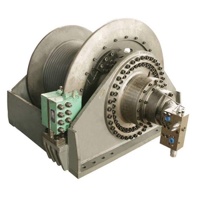
The differences between these three families show up in five spec dimensions: drum configuration (single vs double), free-fall requirement, pull force class, line speed class, and duty cycle rating. The 5m 50t double-drum hydraulic tugger winch with free-fall function in the IYJ-L series is a representative configuration for the barge-work family — it pairs a high-pull (150 kN on first layer) double-drum layout with the wet-type hydraulic brake and clutch required for controlled free-fall release.
Beyond the application family, the regulatory framework also matters. Most working tugger winches on classed vessels fall outside the explicit scope of classification society rules (Lloyd's Register, Bureau Veritas, ABS, DNV, CCS), but the deck reinforcement, fastening, and safety-factor calculations still need to align with the vessel's class. The Lloyd's Register and American Bureau of Shipping technical libraries provide the structural-design guidance that most shipyards follow even for non-classed equipment. The International Maritime Organization (IMO) framework establishes the high-level safety and equipment-performance conventions that classification societies and flag states implement through their rules.
Application 1 — Deck Handling
Deck handling covers the routine line and equipment transfer work that happens between deck levels, between holds, and between the deck and pier-side service craft. The defining characteristic is intermittent duty: a deck-handling winch runs hundreds of short pulls per day but rarely sustains a single pull for more than a minute or two. Cycle rate is high, peak load is moderate, thermal capacity is not the constraint.
Deck Handling — Configuration Profile
Pull class: 5-10 tons · Line speed: 30-80 m/min · Drum: single
Drum configuration
Single drum is the right answer. Deck handling rarely needs a spare drum in operation, and the simpler mechanism reduces the maintenance surface. The drum capacity is sized to the longest single-pull distance plus a safety factor — typically 100-200 m of rope for shipboard applications.
Pull force and line speed
5-10 tons (50-100 kN) is the working range for most deck-handling pulls. Line speed at 30-80 m/min is the sweet spot — fast enough to be productive for utility work, slow enough that operators can manage the line by hand when needed. Higher line speed (above 80 m/min) introduces control difficulties and rope-wear issues for short-distance pulls.
Free-fall requirement
Not required for deck handling. Free-fall adds mechanical complexity (hydraulic clutch and braking system) that is not justified for routine utility pulls. Specify free-fall only if the deck-handling winch will also be used for anchor work or emergency release.
Power source
Hydraulic from the vessel's existing HPU is the right choice for permanent installations. Pneumatic for portable winches that move between vessels. Electric for small deck-handling utility winches where the vessel has AC power available and the duty is light.
Duty cycle rating
Intermittent duty (typically ED 25% to ED 40%) is sufficient. Continuous-duty rating is wasted capacity for deck handling.
Deck handling is the application where mis-specification causes the most frustration: shipyards that order 30-ton continuous-duty winches for routine 5-ton utility pulls end up with heavier, more expensive equipment that is harder to maintain, even though it "works" for the application. Match the spec to the work, not to the maximum possible load.
Application 2 — Barge and Inland-Vessel Work
Barge work is the application where tugger winches earn the right to be called "tugger." The defining work is warping — moving a barge or floating equipment by line pull rather than by tug or pushboat. Warping requires sustained high pull under intermittent control, with frequent free-fall releases for letting line back out under load. Inland construction work (pile-driving support, anchor handling, pipe-laying) shares the same duty pattern with the additional requirement of precise load control during release.
Barge Work — Configuration Profile
Pull class: 30-50 tons · Line speed: 5-15 m/min · Drum: double · Free-fall required
Drum configuration
Double drum is the standard for serious barge work. The second drum either holds a different rope type (working line vs. tag line) or holds spare rope for extended warping operations. On the IYJ-L 50-ton free-fall model, the double-drum layout pairs two independently-controlled drums with a shared planetary gearbox and hydraulic motor arrangement — both drums can operate simultaneously for complex barge positioning maneuvers.
Pull force and line speed
30-50 tons (300-500 kN) is the working range for serious barge warping. Line speed is slower than deck handling — typically 5-15 m/min — because the line is under sustained load and the operator is controlling position, not just transferring equipment. Higher line speed at 50-ton pull force is mechanical over-spec that wears the gearbox and the rope without adding useful work capacity.
Free-fall requirement
Free-fall is required for barge work. The free-fall function lets the drum pay out under load without driving the motor — the load itself drives the drum rotation, controlled only by the wet-type hydraulic brake. This is the safe way to release a stuck barge, lower an anchor, or pay out line during a pile-driving operation. Air-cooled dry brakes cannot sustain the cycle rates that barge work demands; wet-type hydraulic brakes (standard on the IYJ-L series) handle the thermal load.
Power source
Hydraulic from the vessel's HPU is the standard. Pneumatic is uncommon at this pull class because the air consumption for continuous 50-ton pull exceeds what most marine air systems can supply without compressor cycling issues.
Duty cycle rating
Intermittent-to-moderate (ED 40% to ED 60%). Barge work is heavier than deck handling but still does not require continuous-duty rating.
The IYJ-L 50-ton free-fall model carries 4 rope layers at 232 m total drum capacity, with a 28 mm wire rope diameter and a 30 MPa system pressure. The clutch opening pressure at 7.5 MPa determines the free-fall trigger threshold — the line begins paying out under load once the load exceeds the clutch holding torque. For an application-to-spec example, a barge-warping operation that needs 200 m of working rope plus 50 m of spare on the second drum matches the IYJ-L drum capacity exactly without re-spooling.
Application 3 — Terminal and Quay Work
Terminal work happens at the dock side rather than the vessel side. The defining duty is sustained cycle rate — a terminal tugger winch may run hundreds of cargo cycles per shift, with the winch working hard for most of the operating hours. Thermal capacity, not peak pull, is the binding constraint. Terminals also need fail-safe braking under sustained load, because the winch is often holding a load at the limit of its rating during cargo transfer.
Terminal Work — Configuration Profile
Pull class: 10-30 tons · Line speed: 15-30 m/min · Drum: single or double · Continuous duty
Drum configuration
Single drum is standard for most terminal applications, with a second drum added when the operation requires simultaneous working and tag lines. The drum needs to handle high cycle counts without thermal fatigue, which means heavier drum construction (cast or forged steel rather than fabricated plate) and a continuous-duty brake rating.
Pull force and line speed
10-30 tons (100-300 kN) is the working range for terminal cargo handling. Line speed at 15-30 m/min balances productivity with control — terminal operations work at intermediate speed because the cycle is short and the winch is starting and stopping frequently.
Free-fall requirement
Free-fall is optional for terminal work. Most terminal cargo cycles are pull-and-hold, not controlled-release. Specify free-fall only if the terminal handles anchor operations or specific mooring-line release applications.
Power source
Hydraulic from the dock-side HPU is standard. Pneumatic is uncommon for sustained terminal duty. Continuous-duty ratings require an oil cooler on the hydraulic circuit to maintain fluid temperature within specification across the operating cycle.
Duty cycle rating
Continuous duty (ED 60% to ED 100%). Terminal winches run hot and need to be specified for the actual cycle rate, not the maximum pull. A winch rated for 25% duty cycle will fail prematurely in terminal service.
Terminal work is the application where the difference between "catalog spec" and "marine duty rating" matters. Marine winches for terminal service are typically built with larger oil reservoirs, heavier brake packages, and more robust gearboxes than equivalent catalog ratings would suggest. The Society of Naval Architects and Marine Engineers (SNAME) publishes technical bulletins on winch selection and duty-cycle calculation that terminal procurement teams routinely consult.
Pneumatic vs Hydraulic: The Marine Trade-Off
The marine tugger winch market splits roughly into hydraulic (the dominant choice for permanent vessel installations) and pneumatic (the dominant choice for portable service and explosion-risk environments). Electric winches exist but are uncommon for marine tugger duty above the 5-ton class because the starting current and continuous draw exceed what most vessel AC systems can supply without dedicated power conditioning.
Hydraulic tugger winches
- Best fit: Permanent vessel installations with an existing HPU, duty cycles from intermittent to continuous, pull force from 5 tons to 100+ tons.
- Pros: Continuous-duty capacity, high pull force class, integration with vessel hydraulic system, precise control through proportional valve blocks.
- Cons: Requires HPU investment if not already on board, hydraulic fluid contamination risk, more complex maintenance.
Pneumatic tugger winches
- Best fit: Portable service between vessels, explosion-risk environments (tanker decks, fuel-barge work), low-to-moderate pull force class.
- Pros: Mechanically simple, intrinsically safe in flammable atmospheres, no hydraulic fluid contamination risk, easy to deploy on any vessel with compressed air.
- Cons: Limited continuous-duty capacity, lower pull force ceiling than hydraulic, requires substantial air supply for sustained operation, less precise speed control.
Selection rule of thumb
If the tugger winch is going on a vessel that already has an HPU, specify hydraulic. If the tugger winch is going on a vessel without an HPU or in an environment with flammable atmosphere risk, specify pneumatic. Electric stays in the under-5-ton utility niche.
Deck Mounting and Bolt-Pattern Anchors
The deck mounting pattern is the procurement question that gets answered last and most expensively. A wrong bolt pattern means cutting new holes in reinforced deck plating, which is a fabrication job that costs more than the winch itself if done after delivery. Three anchor points should be locked in the procurement specification, not deferred to shipyard detail design:
1. Bolt pattern geometry
Marine tugger winch base frames are rectangular, with bolt holes on the perimeter. The pattern is defined by two dimensions: the longitudinal spacing (along the drum axis) and the transverse spacing (perpendicular to the drum axis). For 5-10 ton class winches, the typical pattern is 8 M20 or M24 bolts on a rectangular grid. For 30-50 ton class winches like the IYJ-L 50-ton double-drum, the pattern expands to 12-16 high-grade bolts (typically M30 or M36) on a larger rectangular footprint.
2. Bolt grade and tightening torque
Marine deck fastening uses high-grade bolts (typically Grade 8.8 or higher in metric, equivalent to Grade 5 or better in SAE). Bolt tightening torque follows the bolt grade, the base-plate thickness, and the deck plating thickness. Specifying bolt grade in the winch data sheet (and verifying it matches the deck reinforcement specification) prevents the procurement gap where shipyard and supplier disagree on the fastener specification.
3. Deck reinforcement
The deck plating under a tugger winch must be reinforced to spread the line-pull loads. For a 5-10 ton winch, doubling the deck plate locally (adding a 6-10 mm reinforcement plate) is typical. For a 30-50 ton winch, the deck reinforcement is heavier — the IYJ-L 50-ton model needs the deck plating below the winch to be at least 12 mm thick and supported by additional stiffeners on a grid pattern matching the bolt-hole layout.
Anchor pattern reference points
For a 5-ton deck-handling winch on a typical working deck: base footprint roughly 600 mm × 500 mm, 8 M20 bolts on a 700 mm × 400 mm bolt-pattern grid. For a 50-ton barge-work tugger like the IYJ-L: base footprint roughly 1,400 mm × 1,000 mm, 12-16 M30 bolts on a 1,500 mm × 850 mm bolt-pattern grid. Confirm the exact pattern with the supplier's certified drawing before shipyard steel is cut.
Procurement Checklist Before PO
Eight items to lock in the purchase specification before issuing the marine tugger winch PO. Missing any one of these becomes a change-order during FAT or installation.
- Application family. Deck handling, barge work, or terminal work. The spec changes materially across the three families.
- Pull force class. Working pull (typical) and maximum pull (peak). Specify both, not just maximum.
- Line speed at working pull. Often faster at light load, slower at full pull. Confirm the speed at the actual working pull, not the no-load speed.
- Drum capacity. Length of rope to be carried. Drum capacity at the chosen rope diameter determines if re-spooling is required.
- Free-fall requirement. Yes or no. If yes, the clutch and brake package changes.
- Power source. Hydraulic from existing HPU, pneumatic from vessel air supply, or electric. Each implies different auxiliary equipment.
- Deck mounting pattern. Bolt count, bolt size, bolt grade, footprint dimensions. Confirmed against shipyard steel arrangement.
- Class society and flag-state requirements. Working tugger winches are typically outside explicit class scope, but documentation packages (FAT procedures, material certificates, load-test records) may still be requested.
For procurement teams evaluating INI marine winches for the first time, the INI marine winch experience page documents the production facility, certifications, and reference installations that support the FAT and class-society documentation requirements. Working from an existing marine-winch platform with documented FAT procedures reduces the procurement risk compared to commissioning a custom design for a single project.
Frequently Asked Questions
What is the difference between a tugger winch and a mooring winch?
A tugger winch is a high-speed, intermittent-duty line-handling winch used for cargo handling, barge work, and shipboard utility pulls. A mooring winch is a low-speed, continuous-duty winch designed to hold a vessel against a dock or another vessel under sustained line tension. Tugger winches run at 30-80 m/min line speed with pull force in the 5-50 ton range and intermittent duty cycles. Mooring winches run at 5-15 m/min with much higher sustained pull force and are typically drum-and-brake designs rather than the planetary gearbox configurations of tugger winches.
Pneumatic or hydraulic tugger winch — which is right for marine service?
Hydraulic tugger winches are the right choice for most marine service because the winch can be powered from the vessel's existing hydraulic power unit (HPU) without adding an air compressor. Pneumatic winches are simpler mechanically and intrinsically safer in flammable atmospheres, but they require a separate air supply and have lower continuous-duty capacity. Choose pneumatic for explosion-risk environments (tanker decks, fuel-barge work) and for portable winches that need to work on multiple vessels. Choose hydraulic for dedicated installations where the HPU is already specified.
What free-fall function does the IYJ-L tugger winch provide?
Free-fall allows the drum to pay out line under load without driving the motor — the load drives the drum rotation, controlled only by a hydraulic clutch and braking system. This is essential for pile-driving, anchor-handling, and pipe-laying operations where the line must release at controlled high speed under load. On the IYJ-L 50-ton free-fall model, the clutch opens at 7.5 MPa and the brake is a wet-type hydraulic brake, which handles the high cycle rates that air-cooled dry brakes cannot sustain. Single-rope free-rotation pull is rated at 100 kg at the IYJ-L rated configuration.
What deck mounting pattern should be specified for a tugger winch?
Most marine tugger winches mount on the deck through a base frame with bolt-hole pattern sized to the winch frame footprint. For 5-10 ton class winches, the base pattern is typically 8 M20 or M24 bolts on a rectangular pattern. For 30-50 ton class winches like the IYJ-L 50-ton double-drum model, the pattern expands to 12-16 high-grade bolts (typically M30 or M36) on a larger rectangular footprint. The deck plating under the winch must be reinforced to distribute the line pull loads, and the bolt holes must align with the vessel's stiffener grid.
What rope diameter is typical for a 50-ton tugger winch?
A 50-ton rated tugger winch like the IYJ-L series uses 28-32 mm wire rope for the primary working drum. The drum capacity at this diameter is typically 200-250 m of rope, which is enough for shipboard utility work and barge handling without re-spooling. Smaller tugger winches (5-10 ton) use 16-22 mm rope, and 30-ton class typically uses 24-28 mm rope. Rope diameter and drum capacity are linked by the drum dimensions specified in the winch data sheet.
How long does it take to deliver a custom marine tugger winch?
Standard catalog marine tugger winches ship 30-45 days from PO. Custom-configured winches (specific drum dimensions, rope capacity, motor model, gearbox ratio, mounting pattern) add 15-30 days for engineering and tooling. For a new vessel under construction, the typical procurement window is 90-120 days before sea trial to allow for engineering review, production, factory acceptance testing (FAT), sea-trial preparation, and on-board installation. Class society witnessed FAT adds another 1-2 weeks depending on the society (LR, BV, DNV, ABS, CCS).
Tianyu Hu
Tianyu Hu is a technical content specialist and export sales representative at INI Hydraulic Co., Ltd., one of China's leading manufacturers of hydraulic winches, slewing drives, and fluid power transmission systems. Through INI Hydraulic's YouTube channel and social media platforms, he produces hands-on technical content — including hydraulic system animations, winch load testing footage, and OEM procurement walkthroughs — that helps international buyers understand INI's product engineering before placing orders. With a background in hydraulic transmission engineering and four years supporting offshore, marine, and construction machinery buyers across Southeast Asia, the Middle East, and Europe, Leo translates complex hydraulic spec sheets into practical procurement guidance for OEM engineers, shipyard procurement managers, and industrial equipment distributors.
Post time: Sep-01-2026