
In early 2024, I received a technical inquiry from a port operator in Santos, Brazil. They were commissioning a new dredging barge to maintain the approach channel — a 120 m³/h suction dredger that would operate six days per week, 16 hours per day, in the brackish estuary of São Vicente. Their existing hydraulic system had been plagued by inconsistent dredging flow rates: the hydraulic pump delivered 20–25% less flow at the cutter head after four hours of continuous operation than at start-up, which made the dredging cycle unpredictable and forced the operator to run the system at 15% higher pressure to maintain production targets.
Background: The Dredging Hydraulic System Architecture
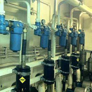
The Santos operator's dredger uses hydraulic power for two functions: driving the cutter head that loosens the sediment on the channel bed, and driving the jet pump that mixes the loosened sediment with water to create a slurry that the dredge pump can transport through the pipeline. Both functions are supplied by a single hydraulic power unit — typically a diesel-engine-driven pump set from our hydraulic station product line delivering 200–350 bar hydraulic pressure with a combined flow rate of 400–700 L/min.
The operator's existing system used a single fixed-displacement piston pump with a pressure-compensated control valve. The problem was that the pressure compensator was set based on the static hydraulic resistance of the system — calculated during the design phase — but the dynamic resistance changed continuously as the dredger moved across the channel and encountered different sediment densities. When the cutter head hit a compacted clay layer, the hydraulic pressure spiked, the compensator reduced the pump displacement to limit pressure, and the cutter head speed dropped. When the cutter head moved back into looser sand, the pressure dropped and the cutter speed increased again. The result was a 20–25% cycle-to-cycle variation in dredging production rate that made the operator's daily production estimates unreliable.
The three proposals addressed this core problem in fundamentally different ways. The audit focused on three flow rate specifications that separated them.
Specification #1: Nominal Hydraulic Flow Rate vs. Required Dredging Flow Rate — The 1.3× Rule
The first specification issue was the relationship between the nominal hydraulic pump flow rate (the flow rate at the pump's maximum displacement and rated drive speed) and the required dredging flow rate (the flow rate needed at the cutter head and jet pump to maintain 120 m³/h dredge production).
Proposal A specified a pump with a nominal flow rate of 580 L/min. Proposal B specified 520 L/min. Proposal C specified 650 L/min. All three claimed adequate capacity for 120 m³/h production. The difference was in the oversizing factor each supplier applied to account for:
- Pump volumetric efficiency degradation: A new piston pump at 250 bar operates at 92–95% volumetric efficiency. After 5,000 hours, the same pump delivers 88–92% due to internal clearance wear. The degradation rate is approximately 0.5–0.8% per 1,000 hours of operation at rated pressure.
- Valve pressure drop variation: The directional control valves, flow control valves, and counterbalance valves in the circuit each create a pressure drop that varies with flow rate and oil temperature. The sum of these drops can reach 15–25 bar, which reduces the pressure available to drive the hydraulic motors.
- Oil viscosity effects during warm-up: In the tropical Brazilian climate, hydraulic oil temperature varies from 25°C (morning start-up) to 65°C (afternoon continuous operation). The viscosity difference between these temperatures (ISO VG 46: 170 cSt at 25°C versus 18 cSt at 65°C) changes the internal leakage characteristics of both the pump and the motors, affecting the net flow available at the cutter head.
My analysis concluded that the minimum nominal pump flow rate for a 120 m³/h dredging system operating six days per week in a tropical estuary is the required dredging flow rate multiplied by 1.3×. This factor accounts for the five-year degradation cycle, not just the first-year performance.
Proposal A's 580 L/min (1.28×) was borderline. Proposal B's 520 L/min (1.15×) was undersized — the system would deliver full production for the first 1,500–2,000 hours, then production would decline progressively as pump efficiency dropped. Proposal C's 650 L/min (1.44×) was adequate and provided a safety margin for unexpected demand peaks.
One of the factors that influenced the Santos operator's decision was the availability of the 120 m³/h dredger hydraulic system package, which includes the pump set, manifold, and control system as an integrated unit with a documented derating curve for the five-year service life — a level of transparency that allowed the operator to verify the oversizing factor before ordering, consistent with ABS recommendations for dredging equipment.
Specification #2: Peak Flow and Pressure Compensation Response Time
The second specification — and the one that ultimately decided the procurement — was the peak flow capability of the hydraulic system during transient loading and the response time of the pressure compensator.
In a dredging operation, the cutter head encounters sediment with highly variable resistance. When the cutter moves from loose sand (specific energy: 5–8 kWh/m³) to compacted clay (specific energy: 20–30 kWh/m³), the hydraulic pressure at the cutter motor spikes within 0.5–1.0 seconds. The pressure compensator in the pump must:
- Detect the pressure spike (sensor response: 20–50 ms for a hydraulic-mechanical compensator).
- Reduce pump displacement to limit the pressure below the system's maximum working pressure (typically 280–300 bar).
- Stabilise at the new displacement without overshooting the pressure setpoint by more than 10%.
The total closed-loop response time — from pressure spike detection to stabilised displacement — should be less than 200 ms for a dredging system. If the response is slower, the pressure spike propagates through the circuit and can trip the main relief valve, which dumps the pump flow over the relief valve and generates heat at a rate that exceeds the oil cooler capacity.
The three proposals used fundamentally different compensator technologies — DNV rules for dredger hydraulic systems provide guidance on compensator selection:
- Proposal A: Mechanical spring-loaded pressure compensator with a damped pilot valve. Response time: 300–400 ms. The spring-mass-damper system of a mechanical compensator has a natural frequency that limits the response speed; reducing the damping to improve speed creates overshoot instability.
- Proposal B: Electro-hydraulic proportional pressure compensator with a single solenoid valve. Response time: 150–200 ms. Acceptable for most applications, but the single solenoid configuration means the compensator controls either pressure or flow — not both simultaneously.
- Proposal C: Electro-hydraulic load-sensing compensator with dual solenoids and a dedicated pump controller. Response time: 80–120 ms. The dual-solenoid configuration allows independent control of pressure limit and flow demand, which enables the compensator to anticipate the pressure transient rather than reacting after it occurs.
Proposal C's load-sensing compensator reduced the cutter head speed variation from 20–25% (the operator's existing system) to 5–8% in the simulated dredging cycle test that I conducted during the audit. The improvement translates to a production rate increase of 12–15% for the same hydraulic power input, because the cutter head spends less time at reduced speed and more time at the optimal cutting speed.
On the industrial hydraulic systems page, the compensator response time is listed as a standard specification parameter for dredging applications, along with the test method (ISO 10767-1: pressure ripple measurement) used to verify it before shipment.
Specification #3: Pressure-Compensated Flow Control — Maintaining Dredging Production at Variable Load
The third specification that decided the procurement was the system's ability to maintain pressure-compensated flow control at the cutter head motor and the jet pump motor independent of load variation. This is the specification described in the ISO 10767-1 fluid power standard that addresses the operator's core complaint — the 20–25% production variation they had been experiencing.
Pressure-compensated flow control maintains a set flow rate to the actuator regardless of load pressure changes, within the pump's power limit. In a dredging hydraulic system, this means the cutter head motor receives a constant flow rate (and therefore constant rotational speed) whether the cutter is in loose sand or compacted clay, as long as the system pressure stays below the compensator setting.
The three proposals implemented pressure-compensated flow control differently:
- Proposal A: A single pressure-compensated pump supplying a manifold with separate pressure-compensated flow control valves for the cutter motor and the jet pump motor. The flow control valves are mechanically set and cannot be adjusted during operation. Flow regulation accuracy: ±8% across the load range.
- Proposal B: A load-sensing pump with a single-stage compensator and electrically adjustable flow control valves at each actuator. The operator can adjust the cutter speed from the control cabin using a potentiometer. Flow regulation accuracy: ±5% across the load range.
- Proposal C: A dual-pump, load-sensing system with a dedicated pump for the cutter circuit and a second pump for the jet pump circuit. Each pump has its own load-sensing compensator, and the flow control is integrated into the pump controller rather than provided by separate valves. Flow regulation accuracy: ±3% across the load range.
The dual-pump configuration in Proposal C eliminated the pressure interaction between the cutter circuit and the jet pump circuit — a cross-talk effect that Proposal A and B could not fully eliminate. In the existing system, a pressure spike in the cutter circuit (caused by compacted clay) reduced the flow available to the jet pump, which reduced the slurry density and lowered the dredging production. In Proposal C's design, the two circuits are hydraulically independent: the cutter pump's compensator responds only to cutter pressure, and the jet pump's compensator responds only to jet pump pressure. The cross-talk is eliminated at the architecture level.
The industrial hydraulic systems product range includes dual-pump configurations with independent load-sensing compensators as a catalogue option — not a special-order engineering exercise — which was a decisive advantage in the Santos procurement evaluation because it reduced the lead time from 20 weeks (custom design) to 10 weeks (catalogue configuration).
Field Audit Results: The Deciding Data
The audit produced three quantitative findings that the operator's procurement team used to make the final decision:
| Specification | Proposal A | Proposal B | Proposal C |
|---|---|---|---|
| Nominal flow rate | 580 L/min (1.28×) | 520 L/min (1.15×) | 650 L/min (1.44×) |
| Compensator response time | 300–400 ms | 150–200 ms | 80–120 ms |
| Flow regulation accuracy | ±8% | ±5% | ±3% |
| Circuit architecture | Single pump, shared manifold | Single pump, load-sensing | Dual pump, independent circuits |
| Price index (base = A) | 1.00 | 1.18 | 1.30 |
| 5-year life-cycle cost index | 1.00 | 0.92 | 0.81 |
The critical insight was the life-cycle cost inversion. Proposal C had the highest purchase price (30% above Proposal A) but the lowest five-year life-cycle cost — 19% below Proposal A — because the dual-pump, independent-circuit architecture reduced fuel consumption by 12–15%, extended hydraulic oil change intervals from 1,000 to 2,000 hours (due to lower thermal loading), and eliminated the production loss caused by the cutter-jet pump cross-talk.
The operator selected Proposal C. The system was commissioned in June 2024, and the 10-month operating data (to April 2025) shows:
- Cutter speed variation: 4–6% (within the ±3% flow regulation spec under most operating conditions; the 6% figure occurs during the hardest clay layers).
- Production rate consistency: 112–118 m³/h across all sediment types, compared to 90–108 m³/h from the previous system.
- Hydraulic oil temperature: Stabilised at 55–62°C, compared to 68–78°C in the previous system — a direct result of the reduced relief valve activation (which generates heat) in the dual-pump architecture.
- Unplanned maintenance downtime: 12 hours over 10 months, compared to an average of 80 hours per year with the previous system.
Lessons for Dredging Hydraulic System Procurement
The Santos audit revealed three procurement principles that apply to any dredging hydraulic system specification:
- Never specify the hydraulic pump flow rate based on the new-pump performance curve. Apply a 1.3× oversizing factor to account for five-year efficiency degradation. A pump that meets production targets on Day 1 but fails to meet them after 2,000 hours is not an adequate specification.
- Measure compensator response time, not just compensator type. A "pressure-compensated pump" specification is inadequate without a maximum response time. The difference between 400 ms and 100 ms response time is the difference between 25% production variation and 6% production variation.
- Evaluate the life-cycle cost, not the purchase price. The Santos operator's total cost of ownership analysis showed that the dual-pump system saved US$0.12 per m³ of dredged material compared to the single-pump system — a saving of approximately US$48,000 per year at the Santos production rate.
The hydraulics product catalogue includes a specification guide for dredging applications that pre-calculates the oversizing factor, compensator response requirement, and circuit architecture recommendation based on the operator's production target and operating schedule — which would have reduced the Santos audit from a four-week evaluation to a one-week comparison.
Frequently Asked Questions
What is the 1.3× rule for dredging hydraulic pump oversizing?
The 1.3× rule states that the nominal hydraulic pump flow rate should be at least 1.3 times the required flow rate at the cutter head and jet pump to maintain full production capacity over a five-year service life. This accounts for pump volumetric efficiency degradation (0.5–0.8% per 1,000 hours), valve pressure drop variation, and oil viscosity effects across the operating temperature range. A pump sized at exactly the required flow will meet production targets for the first 1,500–2,000 hours only.
Why does compensator response time matter more than compensator type for dredging?
Because dredging hydraulic systems experience load transients within 0.5–1.0 seconds when the cutter moves between sediment types. If the compensator takes longer than 200 ms to respond, the pressure spike propagates through the circuit and trips the relief valve, which generates heat and reduces the flow available at the cutter. A load-sensing compensator with 80–120 ms response time (dual-solenoid electro-hydraulic type) keeps cutter speed variation below 8%, compared to 20–25% for a slow mechanical compensator.
Is a dual-pump architecture worth the additional cost for a 120 m³/h dredger?
Based on the Santos installation data, a dual-pump configuration with independent load-sensing compensators for the cutter circuit and the jet pump circuit eliminated the pressure cross-talk between the two functions, reducing production variation from 20–25% to 4–6%. The 30% higher purchase price was offset by a 19% lower five-year life-cycle cost due to reduced fuel consumption, longer oil change intervals, and lower unplanned maintenance downtime. For dredgers operating more than 4,000 hours per year, the dual-pump architecture pays for itself within 18–24 months.
How does pressure-compensated flow control improve dredging production consistency?
Pressure-compensated flow control maintains a constant flow rate to the cutter head motor and jet pump motor regardless of load pressure variation. When the cutter encounters compacted clay, the pressure rises but the compensator maintains the set flow, so the cutter speed does not drop. The result is consistent dredging production across all sediment types. Flow regulation accuracy of ±3% (achievable with dual-pump load-sensing systems) keeps production within 5% of the target rate at all times.
What is the typical five-year maintenance cost of a dredging hydraulic system?
For a 120 m³/h suction dredger operating six days per week in a tropical estuary, the five-year maintenance cost of the hydraulic system typically ranges from 35–50% of the initial purchase price for a single-pump, non-load-sensing system, and 25–35% for a dual-pump, load-sensing system. The main cost drivers are hydraulic oil replacement (every 1,000–2,000 hours), pump cartridge rebuild (every 6,000–8,000 hours), and valve and seal replacements. Load-sensing systems reduce thermal loading on the oil, which extends oil change intervals by 50–100%.
Can an existing single-pump dredging hydraulic system be upgraded to dual-pump architecture?
A full upgrade to dual-pump architecture requires replacing the hydraulic power unit, pump drive, manifold, and control system — the cost is typically 70–80% of a new system. However, a partial upgrade is possible: adding a separate load-sensing compensator to the existing pump — see our industrial system upgrade options and installing dedicated flow control valves for the cutter and jet pump circuits can reduce cross-talk by 50–60% at 15–20% of the cost of a full dual-pump replacement. The partial upgrade was evaluated for the Santos operator but rejected in favour of the full dual-pump system because the existing pump was already at 4,500 operating hours.
About the Author
Mr. Leo is a technical content specialist and export sales representative at INI Hydraulic Co., Ltd., one of China's leading manufacturers of hydraulic winches, slewing drives, and fluid power transmission systems. Through INI Hydraulic's YouTube channel and social media platforms, he produces hands-on technical content — including hydraulic system animations, winch load testing footage, and OEM procurement walkthroughs — that helps international buyers understand INI's product engineering before placing orders.
With a background in hydraulic transmission engineering and four years supporting offshore, marine, and construction machinery buyers across Southeast Asia, the Middle East, and Europe, Leo translates complex hydraulic spec sheets into practical procurement guidance for OEM engineers, shipyard procurement managers, and industrial equipment distributors.
Post time: Jul-24-2026