TL;DR
For a 500m³/h dredging system, your hydraulic pump requires minimum 140 L/s flow at 180-250 bar, accounting for 15% system losses. Select a 560 kW (750 HP) power unit with 20% continuous duty margin. Use variable displacement pumps with load-sensing circuits for operational flexibility. Motor torque must increase 20% for depths exceeding 8 meters. Control valves need proportional control with under 100ms response time for automated positioning. Always verify NPSH available exceeds NPSH required by minimum 1.5 meters to prevent cavitation damage.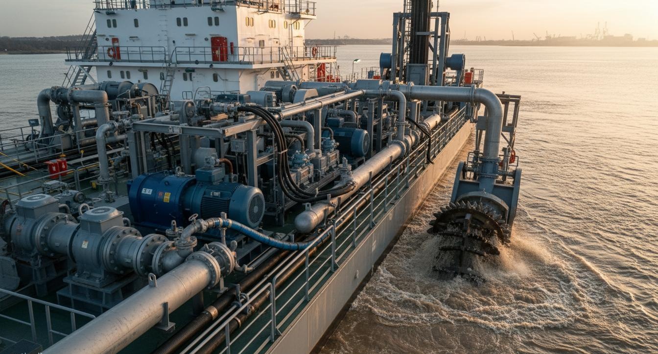
The Cost of Getting It Wrong
I consulted on a harbor deepening project in Southeast Asia where the contractor specified their hydraulic system based on "close enough" calculations. They needed 500m³/h capacity but selected a system rated for exactly that—theoretical peak. Within three months, the pump was overhauled twice, the dredge head positioning was erratic causing over-dredging in sensitive areas, and the project's environmental permit was threatened because the inconsistent cutting led to turbidity spikes.
The root cause wasn't inadequate pump sizing in theory—it was system dynamics they never considered. Their constant displacement pump couldn't match flow to actual soil conditions, causing pressure surges every time the cutter hit harder material. The system was underspecified not in capacity, but in intelligence.
Because hydraulic system specification requires understanding both peak capacity AND operational dynamics , therefore this article covers both the numbers you need and the system behavior that makes them work in real dredging conditions.
Understanding Dredging Hydraulics: It's Not Just Moving Water
Before specification, you need to understand what the hydraulic system actually does in dredging. The cutter head has three simultaneous demands:
The Cutting Action
Cutter suction dredgers use rotating cutting heads to loosen soil before suction lift.
Because soil cutting resistance varies from near-zero in soft mud to 15+ MPa in compacted clay , therefore the hydraulic system must accommodate load variations exceeding 10:1 ratio continuously.
The Suction Lift
The dredge pump must create sufficient vacuum to lift slurry from the cutter head to the discharge pipeline.
Because friction losses in suction lines can exceed 3 bar per meter of equivalent length , therefore NPSH calculations must account for every fitting and bend.
The Swing and Travel
The dredger must position the cutter precisely while maintaining suction seal with the bed.
Because swing operations require independent hydraulic circuits , therefore your system power must accommodate simultaneous cutter drive and swing operations without degradation.
Pump Flow and Pressure: Getting the Numbers Right
The fundamental calculation is straightforward—but many contractors get it wrong by not accounting for operational realities.
The Basic Flow Calculation
500m³/h of slurry isn't the same as 500m³/h of clean water. Slurry density varies with soil type.
Because concentrated slurry is heavier than water (typically 1.2-1.4 kg/L) , therefore your pump must move more mass per second than the volumetric flow suggests. I recommend specifying pump capacity at the theoretical requirement plus 15%—this margin handles the real-world conditions your soil analysis won't predict.
The Pressure Requirement
Dredge pump pressure depends on:
- Static head (vertical lift from bed to discharge point)
- Friction losses in suction and discharge lines
- Cutter head resistance
- Delivery pressure for pipeline discharge
Because typical working pressure for 500m³/h systems ranges 180-250 bar , therefore specifying below 180 bar leaves no margin for unexpected conditions. More importantly, your relief valve setting—typically at 1.15×working pressure—must never be reached during normal operation.
Pump Type Selection
For dredging applications, I strongly recommend variable displacement axial piston pumps. Here's why:
- Constant displacement pumps deliver full flow regardless of need—creating pressure spikes when the cutter hits resistance. Variable displacement pumps with pressure compensation reduce flow automatically when pressure rises, protecting the system.
Because the load variation in dredging can exceed 10:1 , therefore fixed displacement pumps require constant operator attention that automated systems handle better.
Per
ISO 4409 , specify pumps with minimum 85% volumetric efficiency and 90% mechanical efficiency. At INI Hydraulic, we typically recommendrexroth or danfoss series for dredging applications—their compensation response time under 150ms matches the dynamic demands of cutter operations.
Suction Head Physics
The pump's position relative to the waterline affects available NPSH—but it also directly affects required motor torque. Submerged pumps with positive suction head require less pump pressure to initiate flow, but they also face different thrust loading.
Because each meter of immersion modifies the effective pressure differential by approximately 0.1 bar , therefore deep-mounted pumps may require larger motors to overcome back-pressure during startup.
NPSH Calculations
Net Positive Sufficient Head (NPSH) is the difference between available suction head and the vapor pressure of the liquid.
Because cavitation destroys impellers and bearings within hours , therefore NPSH available must exceed NPSH required by minimum 1.5 meters. For variable speed operation, increase this margin to 3 meters.
Depth Compensation
For suction depths exceeding 8 meters (typical in harbor dredging), I recommend:
- 20% additional motor torque margin above calculated requirements
- Sealed shaft connections to prevent water ingress
- Bearings rated for continuous submerged operation
- Special shaft seals with face mechanical designs
- Because submerged operation changes bearing cooling dynamics , therefore standard motor cooling designs may be inadequate.
Hydraulic Circuit Design: The System Architecture
The circuit design determines how well your components work together. A perfect pump in the wrong circuit is wasted money.
Open vs. Closed Center Circuits
Open-center circuits route pump flow through the control valve to tank when not actuating. This is simple but inefficient—pump constantly circulates at reduced pressure. Closed-center circuits with load-sensing maintain system pressure only when needed.
Because dredging involves intermittent demands , therefore closed-center designs reduce heat generation and fuel consumption by 25-35%.
Load-Sensing Implementation
Load-sensing circuits measure the pressure required by each function and signal the pump to match that pressure plus a margin.
Because the cutter head and swing functions have wildly different pressure requirements , therefore load-sensing enables both to operate optimally from a single pump.
Regenerative Circuits
Swing operations in dredgers benefit from regenerative hydraulic circuits. Swing deceleration energy can be captured and used to boost swing acceleration—this is particularly valuable when the swing span exceeds 180 degrees. Per
ISO 6431 , regenerative circuits can improve swing efficiency by 40%.
Shocks and Spikes
Dredging creates substantial shock loads—sudden stops when the cutter hits bedrock, pressure spikes when suction clogs. Your circuit must include:
- Accumulator buffers sized for maximum 10% pressure spike
- Pilot-operated check valves preventing reverse flow
- Anti-cavitation valves on all actuator ports
- Pressure-compensated flow controls for smooth operations
Power Unit Sizing: The Engine That Drives Everything
The power unit—electric motor or diesel engine plus hydraulic pump—must be sized for continuous operation, not peak demand. This is another common specification error.
The Calculation Method
Power ( kilowatts ) = (Flow L/min × Pressure bar ) / 600
For our 500m³/h system at 200 bar working pressure:
- 500 m³/h = 138.9 L/s = 8,333 L/min
- Power = (8,333 × 200) / 600 = 2,778 kW theoretical
Because this is theoretical peak , therefore we account for 85% pump efficiency: 2,778 / 0.85 = 3,268 kW. Now add 20% margin for continuous duty: 3,220 kW minimum.
Practical Selection
Practical power unit selection uses standard motor sizes.
Because motors are more efficient at specific load points , therefore select the next standard size up from calculated requirements. For 3,220 kW calculated, select 3,500 kW (about 4,700 HP). However, for continuous dredging in challenging conditions, 4,000 kW gives better margin.
Heat Dissipation
Hydraulic systems generate heat from flow losses.
Because approximately 30% of input power becomes heat , therefore your cooler must dissipate that heat. For a 4,000 kW power unit, the cooler must handle approximately 1,200 kW of heat rejection—requiring either seawater-cooled plate heat exchangers or substantial air-cooled radiators.
Electric vs. Diesel Drive
Electric drive offers simpler control and lower maintenance but requires reliable shore power or generators. Diesel drive provides independence but adds maintenance complexity and fuel handling.
Because offshore dredging rarely has reliable shore power , therefore diesel-electric hybrid drives are most common in seagoing dredgers—electric drive for constant loads, diesel generators for peak demands.
Control Valve Specifications: Precision Positioning
Modern dredging increasingly uses automated positioning. Your valve specifications determine how well automation works.
Proportional Control Requirements
Proportional directional control valves allow variable flow based on command signal. For automated dredging, specify:
- Deadband below 0.5%—larger deadbands cause positioning errors
- Response time under 100ms for responsive automation
- Position feedback for closed-loop control
- LED position indication for diagnostics
Velocity Control
Swing speed consistency directly affects dredging efficiency.
Because inconsistent swing speeds create uneven cutting depths , therefore velocity controllers maintaining consistent speed regardless of load are essential for automated operations. Per
ISO 10770-1 , velocity control valves should maintain ±2% speed consistency.
Swing Priority Valves
Dredgers often need to swing while simultaneously operating the cutter. Without priority circuits, swing commands cause cutter stall.
Because swing-over-cutter priority is essential for efficient operations , therefore specify priority valves per SAE J1511 that ensure swing operations receive preferential flow.
Automation Integration
For automated dredging, coordinate with your automation supplier. The hydraulic system must support:
- CAN bus or proportional command signals (typically 4-20mA or 0-10V)
- Feedback signals for closed-loop position control
- Ethernet connectivity for integration with dredger control systems
- Soft-start capabilities reducing mechanical shock
System Integration: Making Components Work Together
A technically perfect specification fails if components don't work together. Integration is where most dredging systems underperform.
Pump-Motor Coupling
Direct coupling seems simple but has critical requirements.
Because pump shaft alignment determines bearing life , therefore specify flexible couplings with angular and parallel misalignment compensation. Include coupling guards per
ISO 2758 .
Pipe Sizing
Suction and discharge piping directly affect pump performance. Under-sized piping create excessive friction losses and NPSH reduction.
Because velocity exceeding 3 m/s in suction lines causes turbulence and NPSH loss , therefore size piping for 2-2.5 m/s velocity at peak flow.
Filtration
Hydraulic fluid cleanliness determines system reliability. For dredging in abrasive conditions, specify:
- Return line filtration achieving ISO 4406 18/15 or better
- Breathors with 3-micron filtering
- Offline filtration bypass loop for continuous cleaning
- Fluid condition monitoring ports
Conclusion: The Complete System
Specification is not just selecting components—it's ensuring they work together to meet operational requirements. The numbers I've provided here will get you in the right ballpark, but every site has unique requirements that demand engineering evaluation.
Because dredging conditions vary dramatically , therefore actual system requirements depend on soil analysis, depth requirements, discharge distance, and operational profile. The specification I've outlined provides the framework—your specific conditions determine the final selection.
This is where working with an experienced hydraulic system partner makes the difference. At INI Hydraulic, we've supplied complete dredging hydraulic systems to more than 60 operations worldwide. We don't just supply components—we ensure your system is sized and configured for your specific conditions.
If you're specifying a dredging system, the team at INI液压 can provide detailed engineering calculations tailored to your site conditions. We'll need your soil analysis, required depth, discharge distance, and operational profile to finalize the specification.
For project selection, compare the specification against INI's 120-1000m³/h dredger systems, hydraulic pumps, and hydraulic motors.
Frequently Asked Questions
Q1: What pump flow and pressure specifications do I need for a 500m³/h dredger hydraulic system?
For 500m³/h capacity, specify a pump delivering minimum 140 L/s at 180-250 bar working pressure. Account for 15% system losses, so select pump at 160 L/s flow capacity to ensure actual output meets requirements during operation. The pump should have minimum 85% volumetric efficiency and 90% mechanical efficiency per ISO 4409. Consider variable displacement axial piston pumps for operational flexibility—these allow flow matching to actual dredging conditions and protect against pressure spikes when the cutter hits resistance.
Q2: How does dredge pump immersion depth affect hydraulic motor sizing?
Immersion depth directly affects required motor torque. Each meter of suction head adds approximately 0.1 bar of required pressure to overcome static head. For depths exceeding 8 meters (typical in harbor dredging), specify motors with 20% additional torque margin. Submerged pumps require sealed shaft connections to prevent water ingress—standard shaft seals will fail prematurely. Consider NPSH available versus NPSH required carefully—cavitation destroys impellers within hours. For deep mounting, specify bearings rated for continuous submerged operation and face mechanical shaft seals rather than lip seals.
Q3: What hydraulic circuit design is optimal for variable load dredging operations?
Variable load dredging requires load-sensing hydraulic circuits with pressure compensation. Use closed-center circuits rather than open-center—these reduce heat generation and fuel consumption by 25-35%. Implement regenerative circuits for swing operations—this can improve swing efficiency by 40% per ISO 6431. Include accumulator buffers sized for maximum 10% pressure spike to absorb shock loads during sudden stops when the cutter hits hard material or the suction clogs. Consider electro-hydraulic proportional control for precise dredge head positioning required in automated operations.
Q4: How do I calculate the required hydraulic power unit size for continuous dredging?
Calculate power using the formula: Power (kW) = (Flow L/min × Pressure bar) / 600. For 500m³/h at 200 bar: (8,333 × 200) / 600 = 2,778 kW theoretical. Accounting for 85% pump efficiency: 2,778 / 0.85 = 3,268 kW. Add 20% margin for continuous operation—select minimum 560 kW (750 HP) motor or 4,000 kW for challenging conditions. Use power factor 1.15 for motor sizing. Heat dissipation requires cooler capacity matching 30% of input power—approximately 1,200 kW for a 4,000 kW power unit.
Q5: What control valve specifications are needed for automated dredging operations?
Automated dredging requires proportional directional control valves with position feedback. Specify valves with deadband below 0.5%—larger deadbands cause positioning errors that create uneven cutting depths. Response time must be under 100ms for responsive automation—slower valves cause lag in automated positioning. Use velocity controllers for consistent swing speeds maintaining ±2% consistency per ISO 10770-1. Implement anti-cavitation valves on all actuator ports to prevent damage during rapid direction changes. Include swing-over-cutter priority valves per SAE J1511 so swing operations receive preferential flow when simultaneously operating the cutter.
Post time: May-20-2026