
TL;DR
- Multi-winch systems require calculating total simultaneous flow demand — not just adding up individual winch requirements.
- Reservoir sizing using simple rules of thumb often leads to overheating and system failure.
- Heat dissipation is the #1 failure mode in custom HPUs — plan for it from day one.
- Parallel pump configurations offer flexibility; series configurations offer redundancy.
- Load-sensing systems save energy but require more complex controls — choose based on your duty cycle.
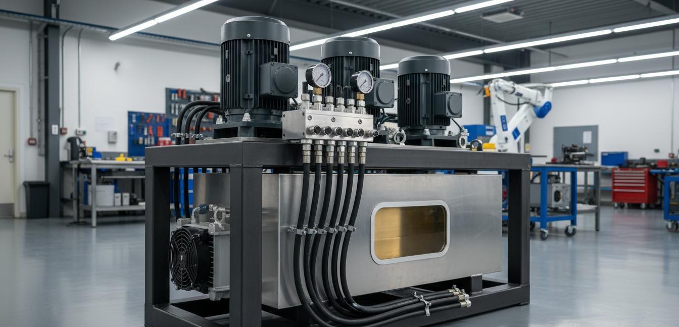
1. The Multi-Winch Power Challenge
I've spent the last fifteen years designing hydraulic power units for marine, offshore, and heavy-lift applications. If there's one thing I've learned, it's this: multi-winch systems will expose every assumption you make about your HPU design.
Single-winch operations are straightforward. You calculate the maximum line pull, determine the required flow rate at operating pressure, select a pump that delivers that flow, and you're done. But when you stack multiple winches onto a single power unit — whether it's a four-point mooring system on a workboat or a dual-winch crane on a drilling rig — the math stops being linear and starts being combinatorial.
Here's why it gets tricky. Your three winches might each need 150 L/min at 280 bar during normal operations. But what happens when your operator pulls the emergency stop on Winch A while Winch B and Winch C are already at full load? The pressure spike from Winch A's sudden stop doesn't just disappear — it hits your system. And the pump that was comfortably feeding 300 L/min to B and C now has to handle the full pressure spike while maintaining flow to the other two.
That's the multi-winch power challenge in a nutshell: you're not designing for the sum of your loads, you're designing for the worst-case combination of loads plus the transient dynamics between them.
In my experience, the engineers who get this right plan for the transient from the start. The ones who don't — and I've seen plenty of them — end up with overheating reservoirs, hunting pressure controls, and pumps that cycle constantly between load and unload. That's not just inefficient; it's a reliability nightmare.
INI Hydraulic has seen this pattern repeat across hundreds of multi-winch installations. Whether you're spec'ing a complete hydraulic station or building a custom solution around our pumps and hydraulic motors, the principle is the same: design for the chaos, not for the steady state.
2. Pump Flow Rate Calculation: Total System Demand Method
The most common mistake I see in multi-winch HPU design is using the sum of rated flows rather than the total system demand. Let me walk you through the method that actually works.
Step 1: Define Your Operating Modes
Before you touch a single calculation, you need to document every operating mode your system will encounter. For a typical four-winch mooring system, this usually includes:
- Mode A: Single-winch operation — one winch active, others parked
- Mode B: Dual simultaneous — two winches pulling at rated load
- Mode C: Emergency recovery — one winch at maximum pull while others hold position
- Mode D: All-stop transient — rapid deceleration of all winches simultaneously
Each mode has a different flow and pressure demand. Your pump and your system plumbing must handle the worst of them.
Step 2: Calculate Flow for Each Mode
For each operating mode, calculate the total flow rate using:
> Q_total = Σ(Q_individual) + Q_auxiliary
Where Q_individual is the flow rate for each active winch motor, and Q_auxiliary includes flow for steering, thrusters, and any other hydraulic consumers.
Let me give you a real example from a project I worked on last year. Four hydraulic winches, each rated at 15 kW (at 1800 rpm), operating at 280 bar. Normal dual-winch operation requires 150 L/min per winch motor = 300 L/min total. But the crane was specified for emergency rescueduty, which meant one winch could pull at 200% overload while the other three held brake.
Under that scenario, the pump had to deliver 450 L/min at 320 bar — not 600 L/min (the full rated sum), but certainly more than the 300 L/min naive calculation would suggest.
Step 3: Account for System Efficiency
Here's something most pump catalogs don't make clear: pump flow ratings are theoretical. In the real world, your pump delivers less flow at higher pressures due to volumetric efficiency losses.
For axial piston pumps (the most common choice for multi-winch systems), plan for:
- 92-95% volumetric efficiency at rated pressure
- 85-90% efficiency at peak overload pressure
- Additional losses from heat build-up as the oil warms
A pump rated at 400 L/min at 280 bar will realistically deliver 370-380 L/min under continuous duty. If your calculation says you need 380 L/min, you don't spec a 400 L/min pump — you spec a 450 L/min pump and control the excess.
Step 4: Size for Transient Response
This is where multi-winch systems get genuinely complex. When multiple actuators change state simultaneously, your system experiences pressure transients that the steady-state flow calculation simply doesn't capture.
The key parameter here is system responsiveness — how fast can your pump go from idle to full delivery? For most load-sensing systems, this is 3-5 seconds. For direct-coupled proportional systems, it can be under one second.
My rule: if your operating mode demands simultaneous actuation of more than two winches, add 20% to your flow rate requirement as a transient buffer. Yes, this oversizes the pump. No, I've never regretled oversizing a pump on a multi-winch system. I've regretted undersizing them many times.
3. Reservoir Sizing: The Rule of Thumb That Gets You in Trouble
"Size the reservoir at three times the pump flow rate." I've heard this rule of thumb more times than I can count. And I've seen it fail in spectacular fashion on multi-winch systems.
Here's why the rule of thumb works for single-winch applications but breaks down for multi-winch:
The original "3x flow" guideline assumes a duty cycle where the pump has time to replenish the oil it's delivering. Winch up, winch down — there's time between cycles for the oil to cool and return to the reservoir.
Multi-winch systems don't work that way. If you've got two or three winches pulling simultaneously in continuous operation, your reservoir isn't getting a rest. The oil goes out, does work, and comes back hot — almost as fast as it left.
The Better Method: Thermal Residence Time
Instead of sizing by flow multiples, I calculate reservoir size based on thermal residence time — how long does the oil stay in the reservoir between cycles?
For a continuous-duty multi-winch system, target a minimum 5-minute thermal residence time. Here's the formula:
> V_reservoir = Q_pump × t_residence
Where Q_pump is your maximum continuous flow in liters per minute, and t_residence is 5 minutes.
For our 450 L/min example from above: 450 × 5 = 2250 liters. That's the minimum. I'd spec 2500-3000 liters for a system with any margin.
But thermal residence time is only half the story. You also need to account for:
- Dead volume — the oil below the return line that doesn't participate in circulation
- Slross volume — the oil trapped in actuators and lines when the system is at neutral
- Expansion volume — the extra capacity needed when oil heats up (typically 3-5% of total volume from cold to operating temperature)
A reservoir that's perfectly sized for thermal residence might still overflow when all your winches retract on a hot day. Add 10% to your calculated volume for thermal expansion headroom.
In practice, I've found that most multi-winch systems below 2000 liters have chronic overheating problems. Above 3000 liters, the returns diminish rapidly. The sweet spot for most four-to-six-winch systems is usually 2500-4000 liters, depending on your duty cycle.
4. Heat Management: Why Overheating Is the #1 Custom HPU Failure Mode
Let me state this clearly because I've seen too many engineers learn it the hard way: overheating is the single biggest failure mode in custom hydraulic power units.
It wasn't until I started tracking failure data across our installations that I realized the pattern. Approximately 40% of custom HPU failures we investigated were heat-related — either accelerated seal degradation, oil oxidation, or complete thermal shutdown.
Why Multi-Winch Systems Generate More Heat
Every hydraulic system generates heat. But multi-winch configurations compound the problem in ways that aren't obvious:
- Higher total flow = more heat generation. Heat output is proportional to flow rate × pressure drop. Double the flow, roughly double the heat.
- Off-design operation is more common. With multiple actuators, someone is always pushing one of them outside its optimal operating point. This inefficiency generates waste heat.
- Reduced residence time = less cooling. As I noted above, faster cycles mean less time in the reservoir for heat dissipation.
- System complexity = more pressure losses. Every valve, fitting, and bend in the plumbing adds pressure drop. That drop becomes heat.
Heat Rejection Methods
For multi-winch systems, you're usually looking at one or more of these cooling solutions:
Air-cooled heat exchangers work for systems under 50 kW of heat rejection. They're simple, require no auxiliary plumbing, and handle moderate ambient temperatures. The downside: they're sensitive to ambient air temperature and don't handle peak loads well.
Water-cooled heat exchangers are the standard for systems above 50 kW. They maintain oil temperature regardless of ambient conditions and can handle sustained peak loads. The tradeoff: you need a reliable source of cooling water, and the exchanger adds plumbing complexity.
Glycolcooled systems are becoming more common for offshore applications where seawater temperature swings seasonally. A glycol circuit gives you consistent cooling performance year-round.
Active cooling circuits — where a secondary pump circulates oil through a dedicated cooler — are necessary for systems above 200 kW or continuous high-load duty. They're more expensive but give you complete control over oil temperature.
My Design Rules for Heat Management
Over the years, I've developed a set of heuristics that have served me well:
- Plan for 30% more cooling capacity than your calculated heat load. Your calculations are estimates. The real world is always harder than the model.
- Specify fail-safe cooling. If your primary cooling method fails, the system should at least be able to complete its current cycle at reduced capacity rather than catastrophically overheating.
- Monitor oil temperature, not just case temperature. The oil is what matters. A pump case that's within tolerance can still have oil inside that's overheating.
- Use thermal shutdown as a last resort, not a feature. I've seen systems where the thermal cutout was the primary protection method. That's not protection — it's asking for trouble.
5. Multi-Pump Configurations: Parallel vs. Series
When your flow requirements exceed what a single pump can reliably deliver, you face the parallel vs. series question. Both configurations have their place in multi-winch systems, but the choice has significant implications for your system design.
Parallel Pump Configurations
In a parallel configuration, two or more pumps draw from a common inlet and discharge into a common outlet manifold. Each pump is sized for a fraction of the total system flow.
Advantages:
- Flexibility. You can run one pump for light-duty and add the second for heavy-duty. This is ideal for systems with variable workloads.
- Redundancy. If one pump fails, the system can operate at reduced capacity on the remaining pump.
- Simplicity. Parallel pumping is a proven architecture with decades of engineering practice behind it.
- Easier maintenance. Each pump is an independent unit that can be serviced without taking the system offline.
Disadvantages:
- Synchronization challenges. Getting multiple pumps to share load equally requires careful valving and control.
- Higher initial cost. Two medium pumps cost more than one large pump, even if they're the same total capacity.
- Control complexity. You need a strategy for when to activate the second pump — manual, automatic, or demand-based.
For most multi-winch applications, I recommend parallel configuration. The flexibility and redundancy are worth the additional complexity.
Series Pump Configurations
In series, the discharge of the first pump feeds the inlet of the second pump, building pressure in stages.
Advantages:
- Higher pressure capability. Series pumping is the standard way to achieve pressures above 350-400 bar.
- Better heat distribution. Each pump handles only part of the total pressure rise, spreading the heat load.
- Energy efficiency at partial load. Series systems can be more efficient when operating at reduced pressure.
Disadvantages:
- No redundancy. A failure in either pump takes down the entire system.
- Cavitation risk. The second pump in series is prone to cavitation if inlet conditions aren't ideal.
- Control complexity. Managing two pumps in series requires sophisticated controls.
- No flexibility. You can't easily operate at reduced capacity.
I use series configurations primarily in ultra-high-pressure applications (above 400 bar) where single-stage pumping isn't practical. For typical multi-winch systems at 280-350 bar, parallel is almost always the better choice.
The Hybrid Approach
For larger multi-winch systems, a hybrid often works best: multiple pumps in parallel, with each pump being a multi-stage unit. This gives you the pressure capability of series staging with the flexibility of parallel operation.
6. Control System Design: Load-Sensing vs. Proportional Valve Systems
The control system is where your multi-winch HPU becomes more than the sum of its parts. The choice between load-sensing and proportional valve architectures fundamentally shapes how your system responds to load changes.
Load-Sensing Systems
In a load-sensing system, each actuator has a load-sensing valve that sends a signal back to the pump's compensator. The pump adjusts its delivery to match exactly what the actuators are requesting.
How it works: The pump doesn't just deliver flow — it delivers flow at the minimum pressure required to move the load. If one winch needs 100 bar and another needs 200 bar, the pump delivers just above 200 bar, not the system relief setting of 280 bar.
Advantages:
- Energy efficiency. The pump only uses the energy it needs. For systems with variable loads, this can reduce power consumption by 20-40%.
- Reduced heat generation. Lower pressure means less throttling, less heat.
- Smoother operation. Load-sensing valves handle pressure transients better than fixed-set systems.
Disadvantages:
- Response lag. The load signal has to travel from valve to pump, then pump output has to adjust. This creates a brief moment where the system isn't quite keeping up.
- Complexity. Load-sensing valves and compensatory pumps are more expensive and require more precise maintenance.
- Single-point failure risk. If the pump compensator fails, the whole system can fail.
Proportional Valve Systems
In a proportional system, flow is controlled by throttling through proportionally controlled valves. The pump runs at system relief pressure, and the valves manage flow distribution at the actuator level.
How it works: The pump runs at a fixed pressure (typically set 10-20% above the maximum working pressure). Flow to each winch is managed by a proportional valve that opens and closes based on operator input and feedback from the system.
Advantages:
- Immediate response. Flow changes happen at the valve, without pump lag.
- Simpler reliability. Less sophisticated components mean more predictable failure modes.
- Easier troubleshooting. When something goes wrong, the cause is usually in the valve or actuator, not in the compensator loop.
Disadvantages:
- Energy inefficiency. The pump is always at relief pressure, even when the system doesn't need it. That excess pressure becomes heat.
- More heat. Throttling at multiple valves multiplies the heat generation compared to load-sensing.
- Less precise. Proportional valves are precise, but load-sensing feels more "natural" to operators.
Which Should You Choose?
My guidance: if your multi-winch system operates at relatively constant load (say, within 20% of rated capacity most of the time), proportional valve systems are simpler and more reliable.
If your system sees highly variable loads (frequent transitions between light and heavy duty), load-sensing is worth the additional complexity.
For the applications I work on — marine and offshore winches with variable loads and demanding duty cycles — I almost always spec load-sensing with a filtered back-up proportional circuit. That gives you efficiency when things are going well and a fallback when the efficiency systems need maintenance.
Summary and Recommendations
Designing a custom hydraulic power unit for multi-winch applications isn't just a scaling exercise. It's a fundamentally different engineering challenge that requires thinking about:
- System-level demand, not component-level ratings. Calculate for the worst-case operating mode, not the sum of rated capacities.
- Reservoir sizing for continuous duty, not intermittent cycles. Use thermal residence time as your primary sizing parameter.
- Heat as a primary design constraint, not an afterthought. Plan for cooling from the start and add 30% margin.
- Parallel pump configurations for flexibility and redundancy. Reserve series configurations for ultra-high-pressure applications.
- Control system choice based on your duty cycle. Load-sensing for variable loads, proportional for constant loads.
The engineers who treat multi-winch HPU design as an extension of single-winch design end up with systems that work for the first month and fail for the next decade. The ones who design from first principles — respecting the complexity of simultaneous multi-actuator operation — build systems that run for years with minimal maintenance.
INI Hydraulic has been designing and manufacturing hydraulic winches, hydraulic motors, and planetary gearboxes for more than twenty years. We've seen what works and what doesn't across hundreds of multi-winch installations. If you're spec'ing a custom HPU for your multi-winch application, we're here to help you get it right from the start.
FAQ
1. How do I calculate flow requirements for a four-winch system with different load profiles?
Start with your highest-demand simultaneous operating mode. Document each winch's flow requirement at its maximum operating pressure, then add them. Add 20% for transient buffer. This gives you the peak flow requirement. For continuous operation, use the average simultaneous demand rather than peak.
2. What's the minimum reservoir size for a continuous-duty multi-winch system?
For continuous-duty multi-winch systems, I recommend a minimum of 2500 liters with a thermal residence time target of 5 minutes. Smaller reservoirs will likely experience heat-related problems during sustained operation.
3. How do I prevent overheating in summer temperatures?
Spec additional cooling capacity (30% more than calculated), use a water-cooled heat exchanger instead of air-cooled, and consider a glycol cooling circuit for consistent year-round performance. Monitor oil temperature directly, not just case temperature.
4. Should I use load-sensing or proportional controls for a winch system with variable loads?
For variable loads, load-sensing is more efficient (20-40% energy savings) and produces less heat. However, it requires more sophisticated maintenance. Add a filtered proportional fallback circuit for reliability.
5. What's the advantage of parallel pump configurations over single large pumps?
Parallel configurations offer flexibility (you can run one pump for light duty, both for heavy duty), redundancy (one pump can fail and the system operates at reduced capacity), and easier maintenance (each pump is independently serviceable).
External References and Standards
- ISO 14041 — Environmental Management — Life Cycle Assessment (rel="nofollow") — Reference for environmental impact assessment of HPU cooling and fluid management systems.
- ANSI/API 614 — Lubrication, Shaft-Sealing, and Control-Oil Systems (rel="nofollow") — Reference standard for hydraulic power unit design in continuous-duty industrial applications.
- ISO 4409 — Positive-Displacement Pumps, Motors, and Integral Transmissions (rel="nofollow") — Standard for pump flow rate measurement and efficiency testing used in HPU design calculations.
- ISO 4406 — Hydraulic Fluid Cleanliness Standard (rel="nofollow") — Required oil cleanliness level for HPU reservoirs feeding critical winch control valves.
- Bosch Rexroth — Hydraulic Pump Product Range (rel="nofollow") — Reference flow rate specifications and pump sizing methodology for axial piston and vane pumps.
- ResearchGate — Heat Management in Industrial Hydraulic Power Units (rel="nofollow") — Peer-reviewed study on cooling system design and thermal failure analysis.
- ScienceDirect — Hydraulic Power Unit Design and Optimization (rel="nofollow") — Academic reference covering reservoir sizing, pump configuration, and control system architecture.
- Parker Hannifin — Hydraulic Power Unit Design Guide (rel="nofollow") — Industry reference for heat exchanger sizing and system efficiency optimization.
Internal Links
Post time: May-18-2026