
In my four years of supporting shipyard procurement teams across Southeast Asia, the Middle East, and Europe, I have noticed a recurring pattern: many OEM engineers treat anchor winches, mooring winches, and positioning winches as interchangeable deck machinery. They are not. Each serves a fundamentally different load case, and specifying the wrong type leads to either oversized equipment that wastes deck space and budget, or undersized equipment that creates a safety liability during the vessel's first storm mooring.
Functional Boundary: What Each Winch Type Does
Before comparing specification sheets, we must establish the operational boundary of each winch type. The distinction is not academic — it dictates the load case that the winch must survive over its design life.
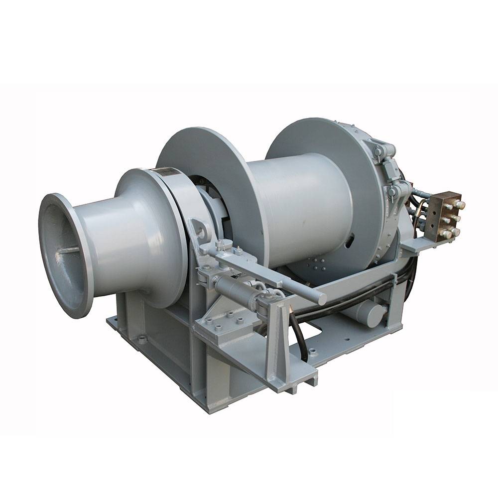
Anchor winch (often called windlass in reference to the vertical-shaft variant) handles the anchor chain or wire rope during deployment and retrieval. The critical load case is the holding load — the peak tension that the winch brake must sustain when the vessel swings at anchor in a storm. Classification society rules typically require the anchor winch brake to hold 80% of the anchor chain's breaking load. For a 50 mm Grade U3 chain, that translates to approximately 520 kN holding force at the drum.
Mooring winch controls the lines that secure the vessel to a berth, dolphin, or buoy. The load case is constant tension — the winch must maintain line tension within defined limits as the vessel rises and falls with tide and swell. A typical mooring winch specification calls for constant-tension control within ±5% of setpoint across a 3–4 metre tidal range. The peak load during spring tide surge can reach 60–70% of the line's minimum breaking load.
Positioning winch (also referred to as station-keeping winch or DP winch) is the most demanding of the three. It operates in dynamic positioning (DP) systems where the vessel maintains position within metre-scale tolerances without anchoring. The positioning winch experiences cyclic loading — repeated tension-and-release cycles as the DP system adjusts thrust. The fatigue design life must typically exceed 10⁶ load cycles. A positioning winch failure during DP operation on a pipe-laying vessel — as documented by ABS DP system guidelines — can halt production at a day-rate cost of US$200,000–500,000.
Several of our clients ask whether the IYM series anchor winch can serve double duty as a mooring winch. The answer is yes — with the correct drum configuration and constant-tension control package — but the reverse is rarely practical. A dedicated mooring winch lacks the holding brake capacity that an anchor winch requires for storm conditions.
Specification Dimension #1: Rated Load and Line Pull
The rated load — commonly expressed as line pull in kilonewtons (kN) or metric tonnes — is the first specification that an OEM engineer checks. But the comparison is not apples-to-apples across the three winch types, because each defines "rated" under a different duty condition.
| Parameter | Anchor Winch | Mooring Winch | Positioning Winch |
|---|---|---|---|
| Rated line pull range | 50–500 kN (typical) | 30–300 kN (typical) | 20–200 kN (typical) |
| Peak holding load | 80% of chain MBL | Line MBL × safety factor | Not applicable (cyclic) |
| Service factor | 1.25–1.5 × rated | 1.5–2.0 × rated | 2.0–2.5 × rated (fatigue) |
| Governed by | Chain breaking strength | Mooring line MBL | DP system thrust demand |
An OEM engineer for a 5,000 DWT cargo vessel should specify an anchor winch with a 100–150 kN line pull, whereas a mooring winch for the same vessel needs only 60–80 kN. The positioning winches on a DP-2 class platform supply vessel typically fall in the 80–120 kN range but require a much higher service factor due to continuous cyclic loading.
Specification Dimension #2: Drum Capacity and Rope/Chain Diameter
Drum geometry is where the physical constraint of deck space meets the functional requirement of wire/chain storage. The three winch types place different demands on drum dimensions, primarily because of the tension gradient from the first layer to the top layer.
Anchor winch drums are designed around chain lockers. The wildcat (the chain-handling wheel) must match the chain pitch and link diameter precisely — a 50 mm chain cannot run through a wildcat machined for 48 mm chain. The drum holds only the length of chain deployed plus three to five shots stored, typically 165–330 metres depending on vessel class.
Mooring winch drums hold wire rope or synthetic mooring lines that can be 200–400 metres long. The first-layer tension is highest because the wire sees the smallest drum diameter. This is why our winch product line specifies both the first-layer line pull and the top-layer line pull — a difference that can reach 25–30% between the first and fifth layers of a typical mooring winch drum.
Positioning winch drums operate with shorter wire lengths — often 50–150 metres — but the wire pays in and out continuously. The drum must be designed with Lebus grooving or equivalent spooling technology to prevent wire crossover damage under cyclic operation. A damaged wire on a positioning winch during a DP operation is not a maintenance issue — it is an operational shutdown trigger.
The IY-N series winch illustrates this trade-off well: it offers interchangeable drum configurations that allow the same winch frame to serve as either a mooring winch with a large-diameter drum or a positioning winch with a Lebus-grooved drum, depending on the spooling insert fitted at the factory — also available in the IYJ hydraulic winch series.
Specification Dimension #3: Brake System Classification
If there is one specification that separates the three winch types more clearly than any other, it is the brake system. The consequences of a brake failure differ radically:
Anchor winch brake failure during anchoring means the vessel drifts. The brake must hold the full design holding load without slipping for 30 minutes per class society testing protocols. This is typically achieved with a band brake acting on the drum rim, applied by a spring-loaded mechanism and released hydraulically. The band brake design is simple, reliable, and self-energising — meaning the load itself increases the brake torque up to the slip point.
Mooring winch brakes must handle dynamic loads — the surge load when a mooring line goes taut as the vessel rises on a swell. The IYJ-C series mooring and positioning winch uses a multi-disc wet brake, which provides smoother engagement and better heat dissipation than a band brake under repeated surge loading. Wet brakes also eliminate the glazing issue that occurs when dry band brakes are used in constant-tension cycling — a common failure mode in mooring winch applications.
Positioning winch brakes face the most severe thermal challenge. Under DP operation, the brake engages and releases hundreds of times per day. The friction material must survive 10⁵–10⁶ engagement cycles without significant wear. Most positioning winches now use spring-applied, hydraulically released (SAHR) brakes with sintered metallic friction discs, which offer consistent torque throughout the service life.
Specification Dimension #4: Control Logic and Automation Interface
The control system is where the three winch types diverge most in terms of cost and complexity — and where OEM specification errors are most expensive to correct after installation.
Anchor winches are typically controlled manually from a local control station on deck. The operator controls pay-out and heave-in speed through a joystick or lever, with a load cell display showing the tension in the chain. Automation requirements are minimal: most classification societies require only an emergency stop and a depth counter.
Mooring winches increasingly require remote control from the ship's integrated bridge system. The constant-tension function — which automatically pays out or hauls in the mooring line to maintain set tension — must interface with the vessel's mooring monitoring system. IMO MEG-4 guidelines (published 2024) now recommend real-time tension monitoring on all mooring winches for vessels over 3,000 GT, which drives the requirement for load cell integration at each mooring station.
Positioning winches require the most advanced control interface. They must integrate with the vessel's DP control system via a fieldbus protocol (typically Profibus DP or CANopen), providing real-time feedback on wire tension, pay-out length, and pay-out speed at a minimum update rate of 10 Hz. The DP controller issues commands to the winch drive as part of the thrust allocation algorithm. This integration is not trivial — I have seen DP commissioning timelines extended by six weeks because the winch control software did not support the required CANopen profile.
Specification Dimension #5: Duty Cycle Classification
The International Organisation for Standardisation (ISO 4301-1) classifies winch duty cycles as M3 through M8 based on the number of operating hours and load spectrum. Each winch type typically falls in a different class:
- Anchor winches: ISO M3–M4. The winch operates only during anchoring and weighing anchor — a few hours per voyage, typically 200–400 hours per year. The load spectrum is dominated by peak loads during break-out of the anchor from the seabed.
- Mooring winches: ISO M5–M6. The winch operates during every berthing and un-berthing event, plus occasional adjustments while alongside. Annual operating hours range from 800 to 1,500, with a moderate load spectrum.
- Positioning winches: ISO M7–M8. The winch operates continuously during DP operations. On a pipe-laying vessel, a positioning winch can accumulate 6,000–8,000 operating hours per year. The load spectrum is severe, with continuous cycling between 10% and 80% of rated load.
The duty cycle classification directly affects gearbox and motor selection. An M4 winch can use a standard planetary gearbox with oil-bath lubrication and a 3,000-hour oil change interval. An M8 winch requires a forced-lubrication gearbox with oil cooler and a 500-hour oil analysis programme.
I recall a specific case from early 2025: a European shipyard specified M4 gearboxes on what should have been M7 positioning winches for a cable-laying vessel. The gearboxes failed at 2,000 hours — exactly on schedule for an M4 component operating in an M7 duty cycle. The replacement cost, including shipyard labour and off-hire time, exceeded the original gearbox cost by a factor of eight.
Specification Dimension #6: Materials, Coatings, and Corrosion Protection
Marine deck machinery lives in a corrosion environment that the International Organisation for Standardisation classifies as C5-M (very high corrosivity, marine). But the three winch types face different corrosion challenges based on their operating location on the vessel:
Anchor winches are mounted on the forecastle deck — the forwardmost deck area that takes the brunt of green water impact in heavy seas. The corrosion protection system must withstand direct seawater impingement. INI uses a three-layer system: zinc-rich epoxy primer (80 µm), high-build epoxy intermediate (150 µm), and polyurethane topcoat (80 µm). All fasteners are A4-80 stainless steel (316 grade).
Mooring winches are distributed along the main deck. They experience salt spray but less direct water impact than forecastle equipment. However, mooring winch drums abrade their paint coating continuously as wire rope runs over them. This is why we recommend flame-sprayed aluminium (FSA) coating on mooring winch drums as a standard option — the metallic coating resists abrasion better than any paint system.
Positioning winches are often installed below deck or in enclosed spaces, particularly on DP vessels where space below the main deck is allocated for winch rooms. The corrosion challenge here is condensation corrosion rather than direct salt spray. A dehumidification system in the winch room, maintaining relative humidity below 40%, extends the coating life of a positioning winch by 5–7 years compared to open-deck installation.
The IYJ hydraulic winch series is available with all three coating specifications depending on the intended deck location, which is why we always ask for the vessel's deck arrangement drawing before finalising the coating scope.
Specification Dimension #7: Classification Society Rules and Certification
Every marine winch installed on a classed vessel must carry type approval or design review certification from the relevant classification society. The rule set that applies — Lloyd's Register (LR), DNV, Bureau Veritas (BV), American Bureau of Shipping (ABS), China Classification Society (CCS), or Korean Register (KR) — depends on the vessel's flag state and the owner's preference. While all societies base their rules on IMO resolution MSC.307(88) (Code for the Construction and Equipment of Ships Carrying Dangerous Chemicals in Bulk, section on deck machinery), each adds specific requirements for winches:
- DNV: Requires dynamic brake testing under load for positioning winches on DP-classed vessels (DNV-OS-E101).
- ABS: Requires mooring winch constant-tension control validation through a 72-hour simulated mooring cycle (ABS Guide for Mooring).
- LR: Requires anchor winch holding brake slip testing at 80% of chain breaking load with a 30-minute hold period (LR Rules for Ships, Part 4, Chapter 8).
- CCS: Adds an additional safety factor of 1.15 on the brake holding capacity for anchor winches installed on vessels operating in Chinese coastal waters (CCS Guidelines for Deck Machinery).
Specifying a winch that is type-approved by the wrong society for the vessel adds four to eight weeks to the certification schedule and cost. We keep product certification documentation on file for all major societies for this reason — switching the certificate is faster than starting the design review from scratch.
Selection Decision Flow
When an OEM engineer approaches me with a new vessel project, the winch selection flows through three questions:
- Primary function: Is the winch deploying or recovering the anchor? → Anchor winch. Is it securing the vessel to a fixed point? → Mooring winch. Is it maintaining vessel position dynamically? → Positioning winch.
- Load condition: Static holding load above 80% of chain/rope MBL? → Anchor winch (band brake). Cyclic loading below 60% of MBL? → Positioning winch (SAHR brake). Intermittent loading at 40–70% of MBL? → Mooring winch (wet multi-disc brake).
- Control interface: Manual control only? → Anchor winch. Remote tension monitoring with constant-tension? → Mooring winch. DP system integration at ≥10 Hz update rate? → Positioning winch.
For all three types, the crane hydraulic dual-winch configuration offers an interesting hybrid — two independently controlled drums sharing a single hydraulic power unit — which some offshore support vessel operators use to combine a mooring winch and a tugger winch on a single foundation.
Practical Example: 10,000 DWT General Cargo Vessel
Consider a concrete example. A shipyard in Batam, Indonesia, recently approached me for a 10,000 DWT general cargo vessel destined for inter-island trade. The specification optimisation broke down as follows:
- Anchor winch: IYM series, 130 kN line pull, single wildcat for 44 mm chain, 247.5 metres of chain storage (15 shots), band brake holding 460 kN. Total weight: 2,850 kg.
- Mooring winches (×2): IYJ-C series, 80 kN first-layer line pull, 250 metres of 24 mm wire rope per drum, constant-tension control with load cell feedback. Total weight per unit: 1,920 kg.
- Positioning winches — not specified: The vessel operates on fixed routes and does not require DP capability. Specifying positioning winches would have added approximately US$85,000 per unit with no operational benefit.
The Y-L free fall winch was evaluated as an alternative for the anchor handling function but rejected because free-fall deployment is not typically required for a general cargo vessel in shallow Southeast Asian ports.
Common Specification Errors
Based on the specification reviews I have conducted for shipyards in Turkey, Vietnam, and the UAE, the most frequent errors are:
- Using the duty cycle classification from the wrong winch type. A mooring winch specified with an M3 duty cycle will fail under sustained constant-tension operation.
- Under-specifying the brake thermal capacity on mooring winches. In ports with a 4-metre tidal range, the mooring winch brake must absorb 5–8 full-energy engagements per berthing. Standard brakes overheat after the third engagement.
- Assuming positioning winch control can be retrofitted to a mooring winch. The DP interface requires firmware changes at the PLC level and additional sensor wiring. Retrofitting costs 40–60% of a new positioning winch.
The full product catalogue on our website includes specification sheets for each winch series with the manufacturer's recommended application domains, which eliminates most of these errors — the same approach advocated by ABS guidelines for mooring equipment at the RFQ stage.
Frequently Asked Questions
Can an anchor winch be used as a mooring winch?
Yes, with the correct drum configuration and constant-tension control package. The anchor winch's band brake must be supplemented with a control valve that allows pay-out under tension. However, the reverse — using a mooring winch as an anchor winch — is not recommended because mooring winch brakes lack the static holding capacity required for storm anchoring.
What is the difference between a positioning winch and a mooring winch?
The positioning winch operates under continuous cyclic loading as part of a DP system, with a fatigue design life exceeding 10⁶ load cycles. The mooring winch operates intermittently during berthing and while alongside, with a constant-tension control that maintains line tension within ±5% of setpoint. Positioning winches require SAHR brakes, Lebus-grooved drums, and DP control integration; mooring winches use wet multi-disc brakes and can operate with simpler tension monitoring.
Which classification society rules apply to anchor winches?
All major classification societies — Lloyd's Register, DNV, Bureau Veritas, ABS, CCS, and Korean Register — have specific rules for anchor winches based on IMO resolution MSC.307(88). The key requirement across all societies is that the holding brake must sustain a load equivalent to 80% of the anchor chain's breaking strength for 30 minutes without slipping. Some societies add regional requirements, such as CCS's additional 1.15 safety factor for vessels operating in Chinese coastal waters.
What drum capacity do I need for a mooring winch on a 10,000 DWT vessel?
For a 10,000 DWT general cargo vessel, a mooring winch drum should hold 200–250 metres of 22–24 mm wire rope. The drum width-to-diameter ratio should be between 1.5:1 and 2.5:1 to ensure acceptable fleet angles at the fairlead. If synthetic mooring ropes (HMPE) are specified, the drum diameter must be at least 12 times the rope diameter to prevent internal rope fatigue.
How much does a marine winch positioning system cool-down time affect DP operations?
The SAHR brake on a positioning winch generates heat proportional to the number of engagement cycles. Most DP operations require a 15–20 minute cool-down window after four hours of continuous positioning. Specifying sintered metallic friction discs (rather than organic linings) reduces the required cool-down time by approximately 40% because metallic discs dissipate heat more efficiently and tolerate higher continuous operating temperatures.
Is free-fall anchor deployment required for all vessels?
No. Free-fall anchor deployment is primarily specified for offshore supply vessels, anchor handling vessels, and ships operating in deep-water harbours where rapid anchoring is required for emergency manoeuvring. For general cargo vessels and bulk carriers operating in standard port conditions, controlled power-lowering deployment is sufficient and reduces wear on the anchor brake system.
About the Author
Mr. Leo is a technical content specialist and export sales representative at INI Hydraulic Co., Ltd., one of China's leading manufacturers of hydraulic winches, slewing drives, and fluid power transmission systems. Through INI Hydraulic's YouTube channel and social media platforms, he produces hands-on technical content — including hydraulic system animations, winch load testing footage, and OEM procurement walkthroughs — that helps international buyers understand INI's product engineering before placing orders.
With a background in hydraulic transmission engineering and four years supporting offshore, marine, and construction machinery buyers across Southeast Asia, the Middle East, and Europe, Leo translates complex hydraulic spec sheets into practical procurement guidance for OEM engineers, shipyard procurement managers, and industrial equipment distributors.
Post time: Jul-16-2026