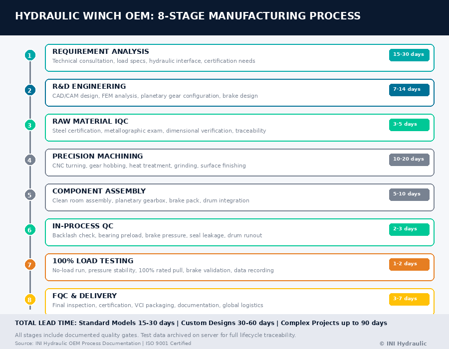
A professional hydraulic winch OEM process spans 8 critical stages — from customer requirement analysis and R&D design through CNC machining, heat treatment, precision assembly, and 100% load testing before shipment . For B2B procurement decision-makers, understanding this full process is essential to evaluating supplier capability, ensuring quality consistency, and mitigating supply chain risk. Leading OEMs like INI Hydraulic maintain ISO 9001 quality systems, GJB82-86 national standards compliance, and 20,000+ hour gear life certification .
1. Stage 1: Customer Requirement Analysis & Technical Consultation
The OEM process begins not with production, but with deep technical consultation. A professional hydraulic winch OEM must first understand:
Critical Input Parameters:
-
Application environment: Marine, construction, mining, or petroleum — each demands different corrosion protection, sealing grades, and duty cycles
-
Load specifications: Rated line pull (1.5 tons to 500+ tons), working speed (3–40 m/min), and rope capacity
-
Hydraulic system interface: Operating pressure (14–20 MPa typical), flow rate (55–150 L/min), and motor flange compatibility
-
Mounting constraints: Installation bracket dimensions, drum orientation, and space envelope
-
Certification requirements: ABS, DNV, CE, or GJB82-86 national military standards
Procurement Insight: OEMs that skip detailed requirement analysis and immediately quote standard models often deliver mismatched products. Professional OEMs invest 3–7 days in technical specification confirmation, providing 3D models (STEP, IGES) and hydraulic circuit simulations before production authorization .
Deliverable: Signed technical specification document, 3D assembly model, and hydraulic performance simulation report.
2. Stage 2: R&D Engineering & Design Validation
2.1 CAD/CAM Design & Finite Element Analysis
Modern OEMs employ computer-aided design supported by Finite Element Method (FEM) simulation to optimize every torque-transmitting component
-
Gear tooth stress analysis: Determines load-bearing behavior and safety factors under peak torque
-
Housing deformation simulation: Ensures structural integrity under 20+ MPa hydraulic pressure
-
Thermal analysis: Predicts oil temperature rise during continuous duty cycles
2.2 Planetary Gearbox Configuration
The planetary gear reducer is the core of hydraulic winch performance. OEMs design multi-stage configurations:
| Stage Count | Typical Ratio Range | Application |
|---|---|---|
| 2-stage | 20–50:1 | Light-duty (1.5–10 tons) |
| 3-stage | 50–150:1 | Medium-duty (10–50 tons) |
| 4-stage | 150–900:1 | Heavy-duty (50–500+ tons) |
Design Principles:
-
Full-float typed planetary gear reducer: Ensures stable operation and rational load distribution
-
Multiple planet wheels: Simultaneously engage sun and ring gears, distributing torque across contact points for 95%+ efficiency
-
Computer-simulated deformation and stress analysis: Optimizes housing and planet carrier design before metal cutting
2.3 Brake System Integration
Safety-critical brake design includes:
-
Multi-disc friction normally-closed arrester: Larger brake torque, safer and more reliable operation
-
Fail-safe disc brakes (EN 13155 compliant): Prevents runaway loads
-
Emergency stop response: <0.5 seconds trigger time
-
Brake release pressure: <2.5 MPa (25 Bar) typical
2.4 Prototype Validation
Before mass production, OEMs manufacture pre-production samples for:
-
Load carrying capacity measurements: High-frequency pulsator and FZG tension tests
-
Operational behavior optimization: Noise levels, vibration characteristics, and thermal performance
-
Hydraulic circuit validation: Pressure stability and flow efficiency under simulated working conditions
Deliverable: Validated engineering drawings, prototype test report, and production-ready BOM (Bill of Materials).
3. Stage 3: Raw Material Procurement & IQC
3.1 Material Specification
Premium hydraulic winch OEMs specify materials exceeding industry standards
| Component | Material Grade | Standard |
|---|---|---|
| Gear sun/planet/ring | Premium hardened and tempered steel | DIN EN 10204 Inspection Certificate 3.1 |
| Drum body | High-strength structural steel | Q345B/Q460C |
| Housing | Ductile iron or cast steel | GB/T 1348 |
| Shafts | Alloy steel, case-hardened | 20CrMnTi / 42CrMo |
| Seals | Viton/NBR high-pressure seals | GB/T 3452.1 |
3.2 Incoming Quality Control (IQC)
Professional OEMs implement 5-stage incoming inspection :
-
Raw material certificate verification: Chemical composition, mechanical properties, and mill test reports
-
Dimensional inspection: Caliper, micrometer, and CMM (Coordinate Measuring Machine) verification
-
Metallographic examination: Grain structure, inclusion rating, and hardenability
-
Surface defect detection: Ultrasonic testing for internal cracks
-
Material traceability: Lot numbering for full lifecycle tracking
Quality Gate: Any batch failing IQC is rejected or downgraded to non-critical components. Only certified materials enter the production floor.
4. Stage 4: Precision Machining & Manufacturing
4.1 CNC Machining Line
Leading OEMs operate advanced CNC equipment including :
-
CNC lathes: Drum body, shaft turning, and seal groove machining
-
Machining centers: Housing milling, bearing seat finishing, and mounting face processing
-
Gear shapers/CNC hobbing machines: Sun gear, planet gear, and ring gear tooth generation
-
Boring machines: Internal drum diameter and bearing housing precision boring
-
Drilling machines: Hydraulic port drilling and mounting hole patterns
Tolerance Requirements:
-
Gear tooth profile: AGMA 2001-D04 standard
-
Bearing seats: H7 tolerance
-
Shaft runout: <0.02 mm
-
Hydraulic ports: G-thread or SAE flange, ±0.05 mm positional accuracy
4.2 Heat Treatment & Surface Engineering
Heat treatment determines gear life and fatigue resistance:
| Process | Purpose | Typical Parameters |
|---|---|---|
| Carburizing | Case hardening of gears | 0.8–1.2 mm effective case depth, 58–62 HRC surface hardness |
| Quenching & tempering | Core toughness | 28–32 HRC core hardness |
| Nitriding | Wear resistance for shafts | 500–700 HV surface hardness |
| Shot peening | Fatigue life enhancement | 0.3–0.5 mm coverage depth |
Quality Verification:
-
Hardness testing: Rockwell or Vickers hardness profiles across tooth cross-section
-
Metallographic inspection: Case depth, microstructure, and carbide distribution
-
Dimensional stability check: Post-heat treatment distortion measurement
4.3 Gear Grinding & Finishing
Precision grinding achieves the profile-corrected teeth required for high-load planetary systems
-
Gear grinding machines: Achieve DIN 4–6 grade accuracy
-
Tooth surface roughness: Ra 0.8 μm or better
-
Profile modification: Tip relief and root relief for optimal meshing under load
5. Stage 5: Component Assembly & Sub-Assembly
5.1 Clean Assembly Environment
Hydraulic winch assembly requires clean room conditions to prevent contamination :
-
ISO Class 8 clean assembly area: Particle count <3,520,000/m³ (0.5 μm)
-
Component washing: Ultrasonic cleaning with filtered solvent before assembly
-
Lubrication: Assembly grease applied to bearings and seals; hydraulic system filled with specified viscosity grade oil
5.2 Planetary Gearbox Assembly
The planetary gearbox assembly sequence:
-
Ring gear installation: Fixed into housing with interference fit or bolted connection
-
Planet carrier assembly: Planet gears mounted on needle bearings, spaced 120° apart for 3-planet configuration
-
Sun gear insertion: Central sun gear meshes with all planet gears simultaneously
-
Bearing preloading: Angular contact bearings preloaded to eliminate axial play
-
Brake pack installation: Multi-disc friction plates and separator plates stacked with specified spring preload
5.3 Winch Drum Integration
-
Drum mounting: Planetary gearbox output flange bolted to drum hub
-
Rope groove machining: Spiral or Lebus grooving for even rope winding
-
Clutch mechanism: Manual or pneumatic clutch for free-wire releasing function
5.4 Hydraulic Motor & Valve Block Integration
-
Motor mounting: Hydraulic motor flange aligned with gearbox input shaft; coupling or direct spline connection
-
Valve block assembly: Pressure relief valve, balance valve, and shuffle valve manifold mounted per customer specification
-
Hydraulic hose routing: High-pressure hoses (rated 2× working pressure) connected with proper bend radius
6. Stage 6: In-Process Quality Control (IPQC)
6.1 Routing Inspection During Mass Production
Professional OEMs implement full inspection and routing inspection during assembly :
| Inspection Point | Method | Acceptance Criteria |
|---|---|---|
| Gear backlash | Dial indicator | 0.1–0.3 mm (per design spec) |
| Bearing preload | Torque wrench | Per assembly drawing |
| Brake release pressure | Hydraulic test bench | <2.5 MPa |
| Seal leakage | Pressure hold test | Zero leakage at 1.5× working pressure |
| Drum runout | Dial indicator | <0.5 mm TIR |
6.2 100% Functional Testing
Every assembled winch undergoes comprehensive testing before leaving the factory :
Test Sequence:
-
No-load running test: 30 minutes at rated speed — monitor noise, vibration, and temperature
-
Pressure stability test: Hydraulic system held at maximum working pressure for 10 minutes — verify seal integrity and pressure drop <5%
-
Load test: 100% rated pull for 15 minutes — measure drum temperature rise, hydraulic oil temperature, and brake holding capacity
-
Overload test: 125% rated pull for 5 minutes (destructive test on sample basis only)
-
Brake validation: Static hold test at 150% rated load — verify zero slippage
-
Free-wire release: Clutch engagement/disengagement cycle test
Data Recording: All test data saved on computer server for traceability
7. Stage 7: Final Quality Control (FQC) & Certification
7.1 Final Inspection Checklist
Before shipment, each unit undergoes :
-
Visual inspection: Paint finish, marking completeness, and cosmetic defects
-
Dimensional verification: Critical mounting dimensions and interface confirmation
-
Torque mark verification: All fasteners marked with torque seal paint
-
Documentation review: Test report, material certificate, and operation manual completeness
7.2 Certification & Compliance
| Certification | Scope | Relevance |
|---|---|---|
| ISO 9001 | Quality management system | Mandatory for OEM credibility |
| GJB82-86 | Chinese national hydraulic winch standard | Military and heavy industrial applications |
| CE | European machinery directive | EU market access |
| ABS/DNV | Marine classification society | Offshore and shipboard applications |
| AGMA 2001-D04 | Gear rating standard | Gear design and manufacturing quality |
7.3 Packaging & Preservation
-
Rust prevention: VCI (Volatile Corrosion Inhibitor) film wrapping + desiccant packets
-
Sealed hydraulic system: Ports capped with plastic plugs; reservoir filled with preservative oil
-
Export packaging: Fumigation-free plywood crate or steel frame, suitable for long-distance transportation
-
Documentation pouch: Packing list, test certificate, operation manual, and spare parts list attached to crate exterior
8. Stage 8: Delivery, Installation Support & After-Sales
8.1 Logistics & Delivery
Standard OEM delivery terms :
-
Lead time: 15–30 days for standard models; 30–60 days for customized designs
-
Shipping terms: FOB, CIF, or EXW per customer preference
-
Minimum order: One 20' full container (FCL) or LCL (less than container load) acceptable
8.2 On-Site Commissioning Support
Professional OEMs provide :
-
Technical installation guidance: Mechanical mounting, hydraulic plumbing, and electrical connection
-
Pressure and flow calibration: Matching winch to host machine hydraulic system
-
Operator training: Safe operation, daily maintenance, and emergency procedures
-
Load testing witness: Third-party inspection (ABS, DNV) supported on request
8.3 After-Sales Service & Spare Parts
-
Warranty: 12 months or 2,000 operating hours, whichever comes first
-
Spare parts availability: Gear sets, brake packs, seals, and bearings stocked for 10+ years
-
Technical support: Remote diagnostic support and on-site service team dispatch
-
Maintenance recommendations: Detailed service intervals and inspection checklists provided
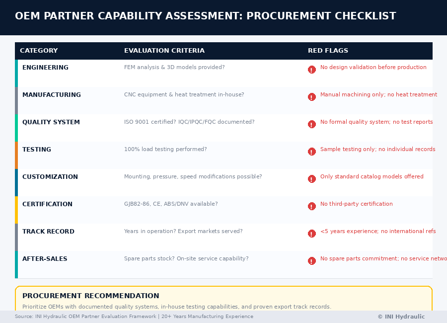
9. OEM Capability Assessment: A Procurement Checklist
When evaluating hydraulic winch OEM partners, verify these capabilities:
| Assessment Category | Key Questions | Red Flags |
|---|---|---|
| Engineering | Do they provide FEM analysis and 3D models? | No design validation before production |
| Manufacturing | What CNC equipment do they operate? | Manual machining only; no heat treatment in-house |
| Quality System | Is ISO 9001 certified? IQC/IPQC/FQC documented? | No formal quality system; no test reports |
| Testing | Do they perform 100% load testing? | Sample testing only; no individual unit records |
| Customization | Can they modify mounting, pressure, and speed? | Only standard catalog models offered |
| Certification | GJB82-86, CE, ABS/DNV available? | No third-party certification |
| Track Record | Years in operation? Export markets served? | <5 years experience; no international references |
| After-Sales | Spare parts stock? On-site service capability? | No spare parts commitment; no service network |
10. FAQ: Hydraulic Winch OEM Process
Q1: What is the typical lead time for a custom hydraulic winch OEM order?
A: Standard models: 15–30 days. Customized designs with non-standard drum dimensions, special mounting brackets, or unique hydraulic parameters: 30–60 days . Complex projects requiring prototype validation may extend to 90 days.
Q2: What technical documents should an OEM provide before production?
A: Professional OEMs deliver: 3D assembly model (STEP/IGES), hydraulic circuit schematic, performance calculation sheet, material specification list, and quality control plan — all subject to customer approval before metal cutting .
Q3: How does an OEM ensure gear quality and longevity?
A: Through:
(1) premium hardened/tempered steel with material certificates
(2) AGMA 2001-D04 compliant gear cutting and grinding ;
(3) controlled carburizing heat treatment with metallographic verification; and
(4) 20,000+ hour design life validation through FZG testing .
A: OEM (Original Equipment Manufacturing): Customer provides design/specification; factory manufactures to exact requirements with customer's branding . ODM (Original Design Manufacturing): Factory provides existing design platform; customer selects from catalog with minor modifications and private labeling.
Q5: Can an OEM modify hydraulic winches for specific operating pressures?
A: Yes. Professional OEMs customize balance valves, relief valves, and motor displacement to match customer hydraulic systems (14–20 MPa standard range, higher pressures available for special applications) .
Q6: What testing validates brake system safety?
A: Multi-disc friction brakes undergo:
(1) static hold test at 150% rated load; (2) dynamic braking test during loaded lowering;
(3) emergency stop response verification (<0.5 seconds); and
(4) 1,000+ cycle fatigue testing for brake pack validation .
Q7: How are hydraulic winches protected during ocean shipping?
A: VCI film wrapping, preservative oil fill, sealed port plugs, fumigation-free plywood crates, and shock-absorbing mounting within the crate. Desiccant packets maintain <40% relative humidity .
11. Conclusion: The OEM Partnership Imperative
The hydraulic winch OEM process is not merely manufacturing — it is engineering partnership. From the initial technical consultation through FEM-validated design, precision machining, 100% load testing, and global after-sales support, each stage determines whether the final product delivers 20,000+ hours of reliable service or fails prematurely in the field .
For B2B procurement professionals, selecting an OEM partner demands rigorous capability assessment. The cheapest quotation often conceals shortcuts in heat treatment, skipped load testing, or non-certified materials. Conversely, OEMs that invest in ISO 9001 systems, GJB82-86 compliance, FEM simulation, and computerized test data archiving deliver the predictability and traceability that global construction, marine, and mining operations require.
As infrastructure investment accelerates across Asia-Pacific, Africa, and Latin America — driving the winch market toward USD 2.8 billion by 2034 — the OEMs that master this full process will define industry standards. The others will be relegated to commodity supply, unable to meet the technical and documentation demands of premium B2B buyers.
About the Author: The INI Hydraulic Engineering Team brings 20+ years of OEM experience in hydraulic winch design and manufacturing. Our ISO 9001-certified facility produces planetary gear hydraulic winches from 1.5 tons to 500+ tons, serving construction, marine, mining, and petroleum OEMs across 40+ countries.
Post time: May-09-2026